Coaster Project
Introduction
What you’ll need
- Piece of pine (or other soft) wood.
- 1/8″ Endmill
- 1/8″ Collet (to hold your 1/8″ endmill)
- Double Sided Tape
Coasters are a great first project! They are useful, customizable, and easy to create. For this project we are going to make 2 coasters. If that is too many for you, or not enough, feel free to modify and customize after you have completed the original tutorial!
Material: Sometimes you can do a design before you know what material you’ll be using, but in most cases you’ll at least need an idea of material type before you begin the design.
The coasters are going to be made from regular pine wood. Pine is cheap and widely available, machines very easily, and can be finished in a variety of ways to make it look great!
Part 1: Design
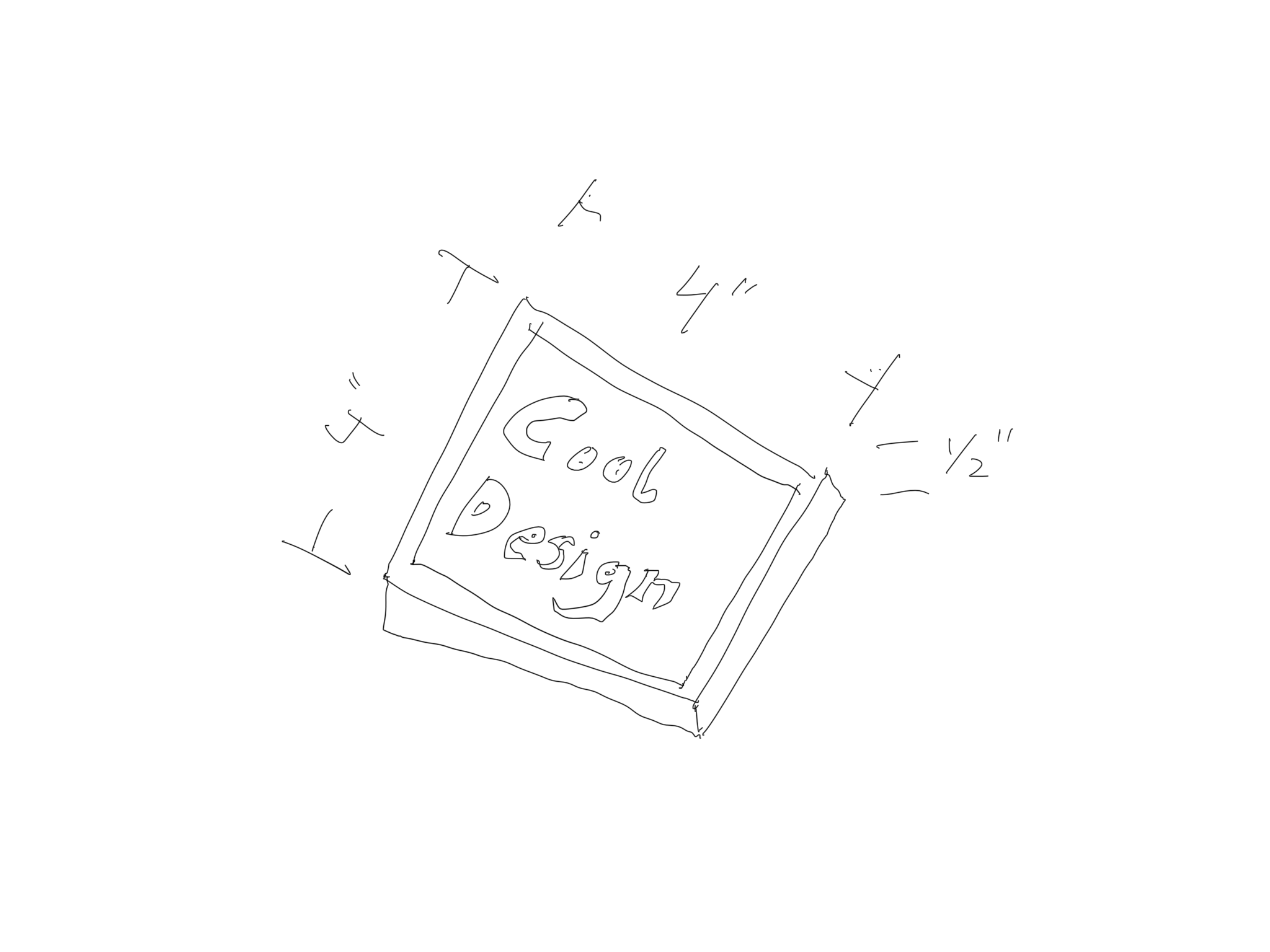
If you’ve seen any of my project videos on youtube, you know I like to start all of my projects with a sketch. This is no exception. Sketching gives you a chance to figure out rough dimensions, and is a great way to visualize the entire project. During this process you can identify any potential stumbling blocks, and give yourself enough information to begin drawing the project with Carbide Create.
To sketch something like this, find a glass or bottle or cup, something representative of what you may set down on the finished coaster. We need to figure out what a good size for the coaster will be, big enough to fit most common vessels, but not so large as to take up unnecessary space.
- Water Glass = 2.25″ Diameter
- Beer Bottle = 3.125″ Diameter
- Water Bottle = 3.25″ Diameter
- Coffee Mug = 3.75″ Diameter
Looking at these dimensions, the coaster should be 4″ square.
With the sketch done, and our dimensions and material selected, we can start drawing the coaster in Carbide Create.
What is Carbide Create?
Carbide Create allows you to draw and create toolpaths. It is known as a CAD/CAM program because it does both digital drawing, CAD (Computer Aided Design) and CAM.
What is CAM?
CAM (Computer Aided Manufacturing) is a program that allows you to turn a drawing file into a language that your CNC machine can understand. This language is called G-Code.
Carbide Create lets you visually define your toolpaths by clicking and selecting from a few options, and when everything is done, Carbide Create generates the G-Code for you.
Carbide Create
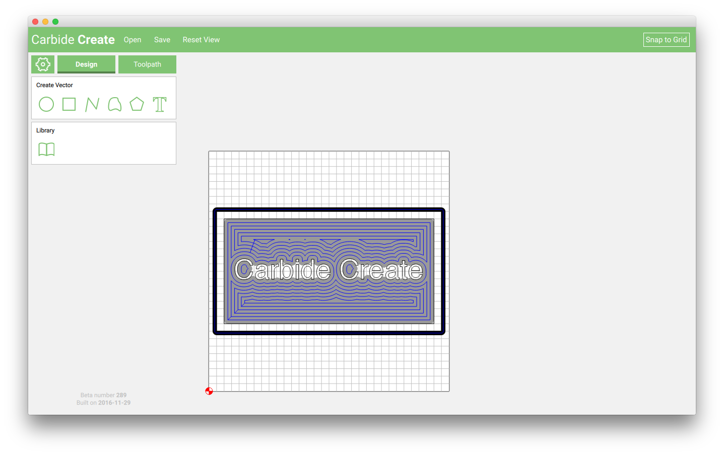
When you open Carbide Create (CC or short), in some versions you will be presented with a default job already in place on the canvas.
We need to clear the canvas (if necessary), and setup our job. To do this, click the Job setup icon.
Design Job Setup
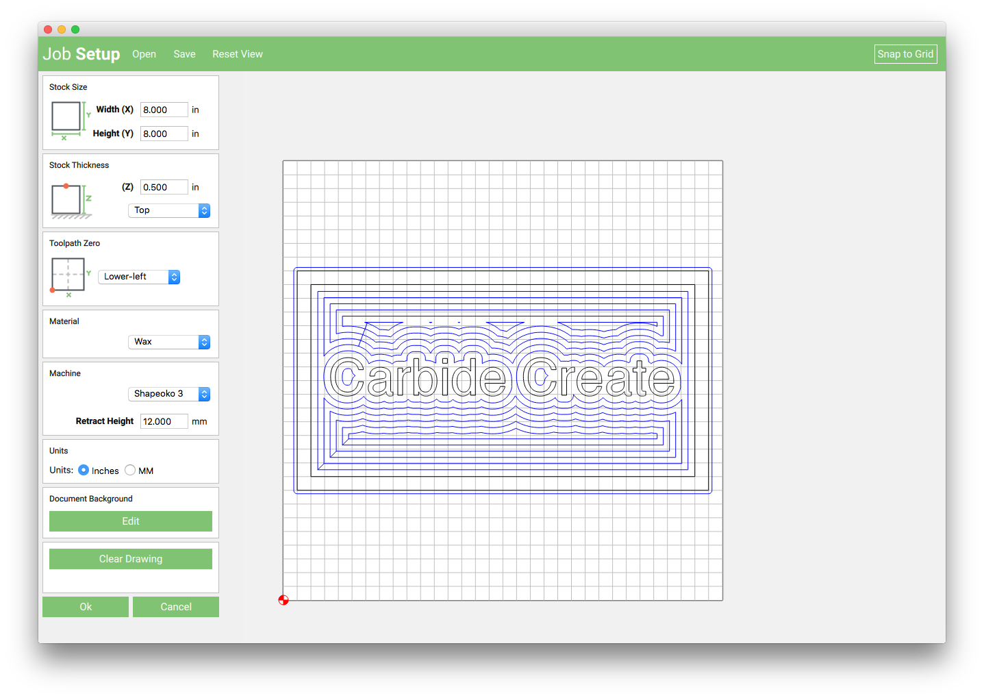
The Job setup screen is where all of the variables for a job are defined. Below you will find an explanation of all the options on this screen.
- Stock Size: Defines the stock size by inputting the actual size of your raw material or a known size for your design. Units entered here can be inches or millimeters, and are defined at the bottom of the job setup screen.
- Stock Thickness: Stock Thickness defines how thick your material is. Utilize best practice by actually measuring your material and entering the actual value measured.
- Z-Zero: Set the Z-zero location by selecting
ToporBottomfrom the dropdown menu found in the Stock Thickness pane. Unless you have a specific reason, or know what you’re doing, always set Z-zero to the top of the material. - Toolpath Zero: Set the starting point of your job by selecting from the dropdown menu in the toolpath zero section. Note the zero point of your job will be represented by the red/white circle shown on the canvas.
- Machine Selection: Set the machine and material by using the dropdown boxes. Selecting the appropriate material will allow Carbide Create to produce accurate speeds and feeds. Selecting the correct machine will define
maximum material sizeandAutomatic feeds and speeds. - Retract Height: Defines how high above the material the machine will retract during rapid moves. Set to a height which clears all clamping, if any.
For this job, we want to set the following parameters: Stock Size: 10″ × 5″ × 1/2″ Toolpath Zero: Center Material: Softwood Machine: Shapeoko 3 (select your machine) Retract height: 12.00mm (this is the default) Units: inches
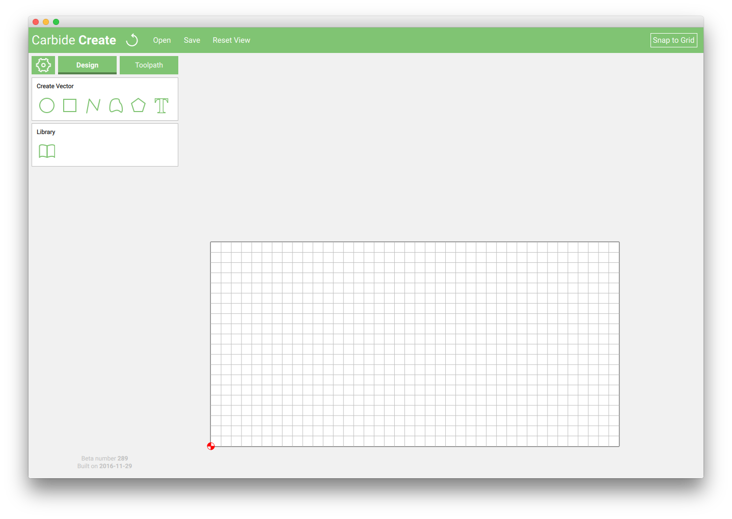
Click 'Clear Drawing' to clear the default design
Click "OK" to apply the changes
Your program should now look like this:
Drawing the coaster
We could make this very simple and just draw a 4″ square. But, we’re better than that!
Instead, let’s look at 2 other options:
Option 1 — use the built in design tools to create a feature design for the coaster.
Great results can be made by adding text to your design. In the following example, I select the text feature, and use Helvetica Bold as the font, then change the heigh size to 3.5″ to place the letter ‘K’ in the coaster.
Use the alignment tools to make sure the two features (the 4″ square and the letter ‘K’) are aligned, both vertically and horizontally.
Option 2 — import an SVG file from another design program or from the internet.
If you are already comfortable designing in another software package (such as Adobe Illustrator, CorelDraw, Inkscape, or Autodesk Graphic) then you could do the design in that program, save the SVG file, and import it into Carbide Create to do the toolpaths!
For this example though, I’m going to download an SVG file from the internet, and use that for the coaster design.
A tip for searching through google images for SVG files: Under settings, set the advanced search feature to only look for SVG!
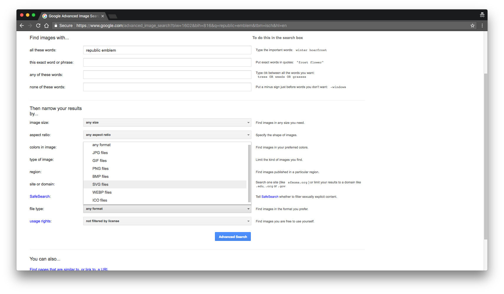
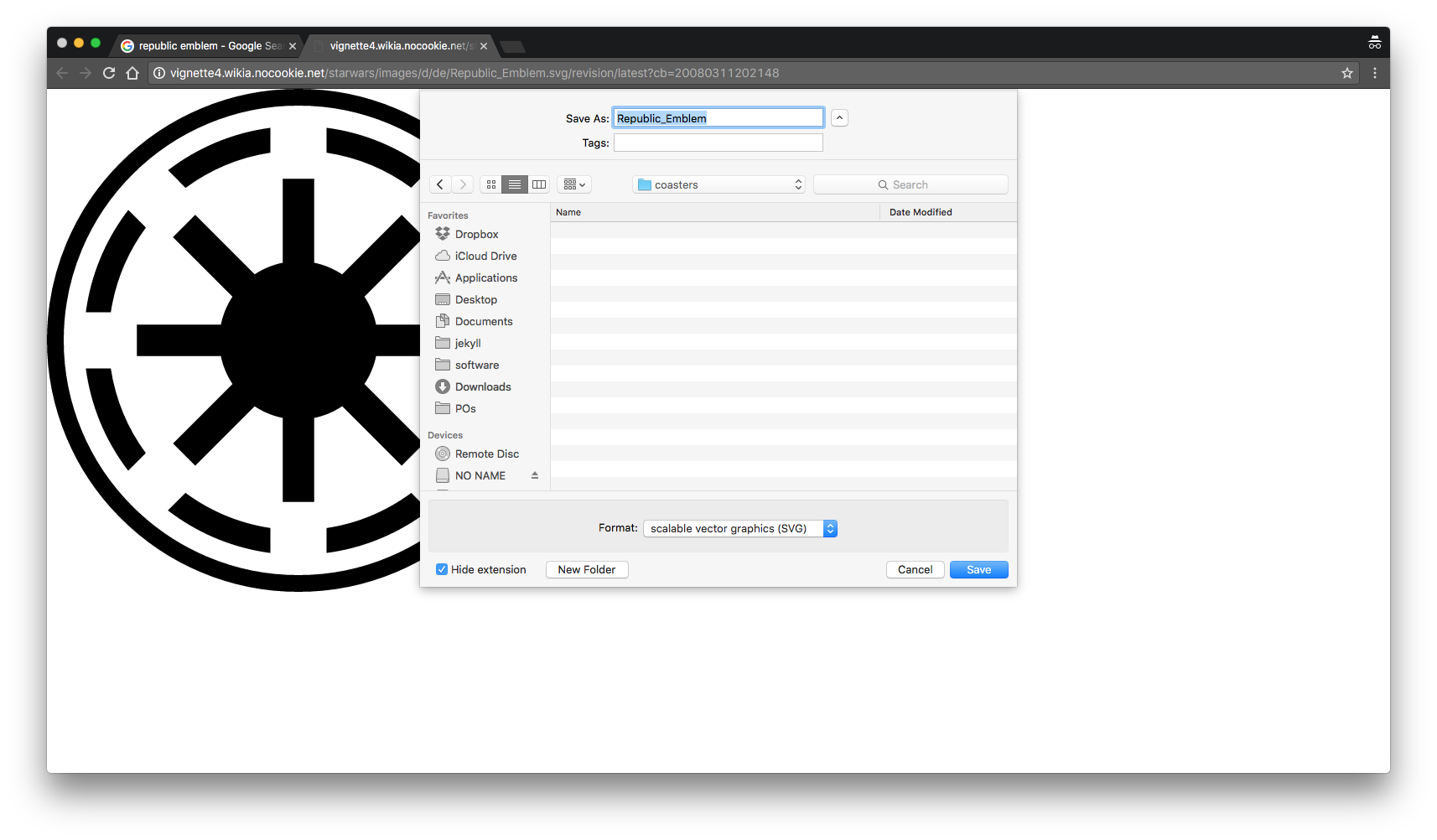
I chose the Republic Emblem from Star Wars, and saved the SVG file to my computer.
Then I opened the file in Carbide Create.
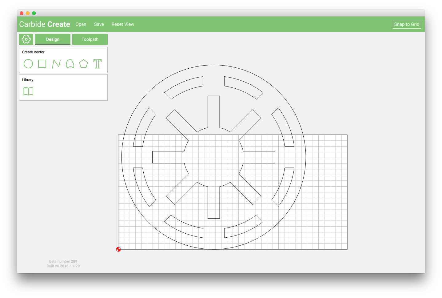
The original file is much larger than we need, in order to use the file, we’ll need to scale it down. CC has a built in scaling feature that will proportionally scale what is selected.
Scale the image down to a maximum (width or heigh, whichever is larger) to 3.5″. Then use the Rectangle tool to draw a 4 inch square around the design.
To maximize our material usage, let’s duplicate the design and make 2 coasters.
- Press ctl + a or command + a to select all (or drag select with your mouse).
- Press ctl+c or command + c to duplicate the design.
Creating the Toolpaths
Our design is finished! Now we need to create our toolpaths.
What are toolpaths?
Toolpaths are the instructions you will create visually to tell your machine HOW to cut your features.
1. What does that actually mean? Toolpaths are the ‘route’ your cutter will take in order to create your part. We use Carbide Create to define these paths. In this section we will select our cutter, feed/speed, and pick which operations to perform on which features.
There are 4 types of toolpaths to choose from:
- Inside Cut - puts the cutter on the inside of the feature
- Outside Cut - puts the cutter on the outside of the feature
- Pocket - clears everything INSIDE of the feature selected.
- No Offset - cuts directly on the line
Create a pocket operation for the center feature
To do so, highlight the features we want to machine (the center star designs) — hold the command (or shift) button to select both objects.
-
Click the ‘Contour’ button found in the top left of the screen to bring up the Edit toolpath screen. This screen lets us select which cutter we will use, how deep to cut, and what type of toolpath we want to use.
-
Cutter: For this design we are going to use a 1/8″ square endmill. Click ‘EDIT’ in the tool section, then select #102 from the dropdown menu. Click OK to return to the toolpath dialog. The speeds and feeds will be calculate automatically!
-
Max Depth: This is how deep we want the feature to be cut. For something like this, we just want to create a little relief, so it doesn’t need to be too deep. Enter 0.063 inches.
-
Offset Direction: Select Pocket because we want to clear out EVERYTHING inside the feature.
-
Name the operation: This might seem trivial, but it’s a good habit to get into for when you start making more complicated parts.
After clicking OK your screen should look like this:
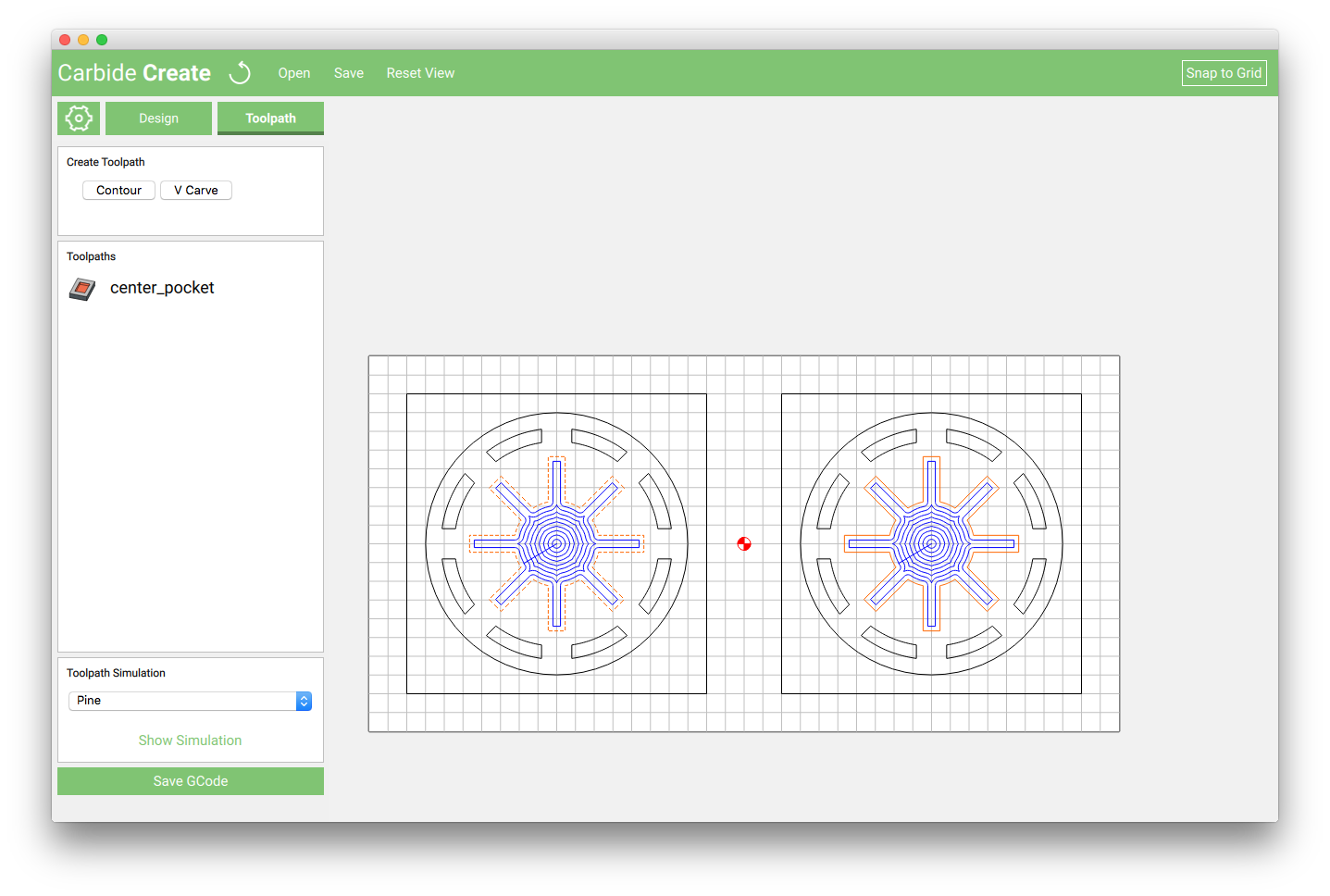
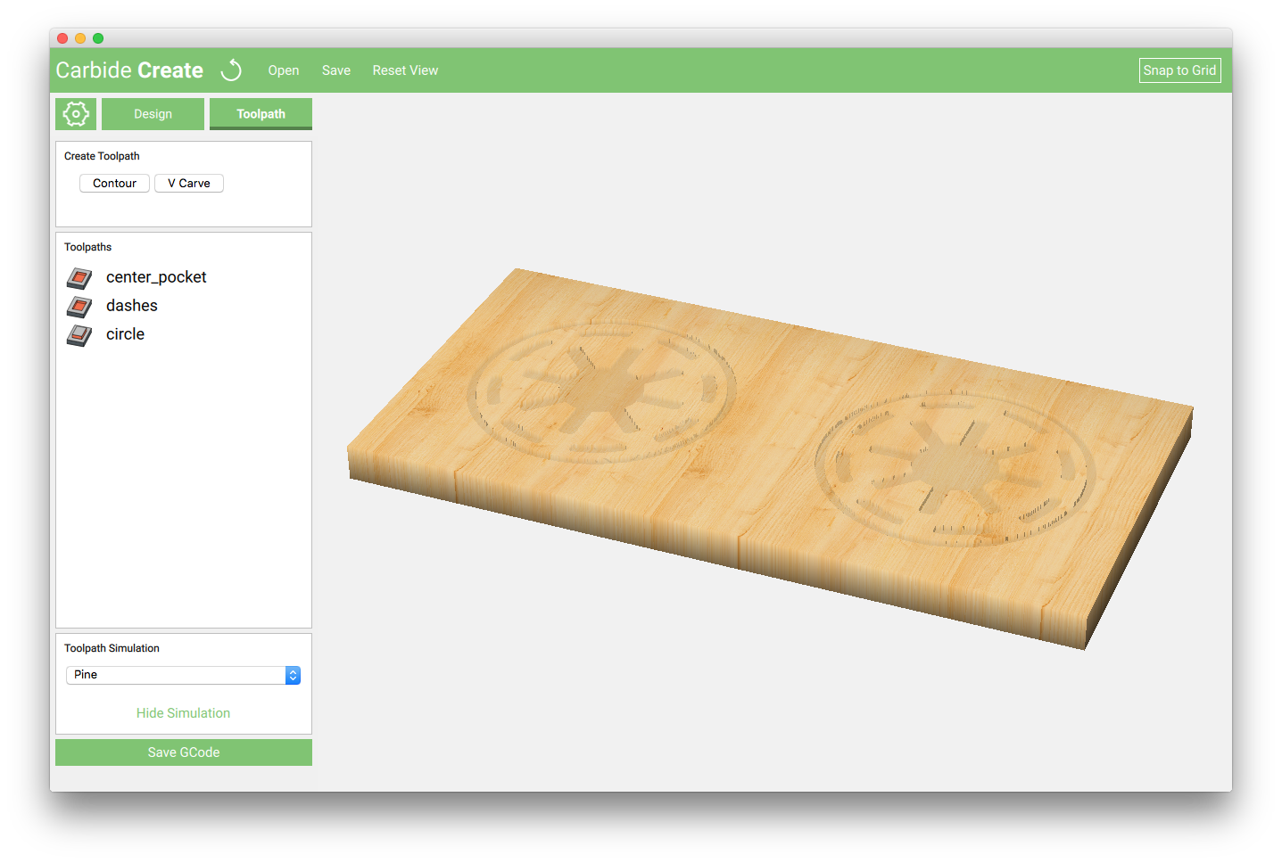
If you select PINE from the toolpath simulation dropdown menu, then click ‘Show Simulation’ to preview what your part will look like.
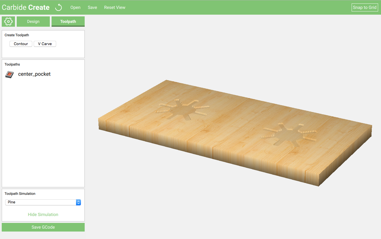
Click ‘Hide Simulation’ to close the preview, and let’s get back to making toolpaths!
Create a pocket operation for the dashes
Select all of the dashes around the center feature. An easy way to do this is to select everything, and then de-select the stuff we don’t want by holding ctrl or command button while clicking.
With the dashes selected, click the Contour button again and set the parameters.
- Cutter: Carbide Create will remember the last cutter you used. As long as you selected the .125″ cutter last time, the program will default to the same.
- Max Depth: We want this feature to be the same as the previous, enter 0.063 inches.
- Offset Direction: Select Pocket because we want to clear out EVERYTHING inside each of the features.
- Name the operation: This might seem trivial, but it’s a good habit to get into for when you start making more complicated parts.
Create the circle around the design
For the circle, we want to engrave this feature into the wood, select the ‘No Offset’ option to perform this action.
Click the Show Simulation button to preview what our design will look like.
Create Profile Cuts Around the Design
The last thing to do is to create the operation to actually cut our designs free from the material!
When creating the profile cut, we select Outside/Right because we want the cutter to cut through the material OUTSIDE of the line to preserve the 4″ dimension.
Selecting the correct ‘Max Depth’ setting is critical! It is good practice to actually measure your material thickness and enter the exact value. If you enter a value that is too small, the cutter will not make it all the way through the material and will require additional cleanup.
Any time you are going to be creating a profile cut make sure it is the last operation of your job. once the profile cut happens, your part will no longer be secured to the material, so any subsiquent operations will either throw your part across the room, or will not turn out right, or both.
With the design finished, and all of your toolpaths created, take a look at the simulation one more time to make sure your part looks like it is supposed to look.
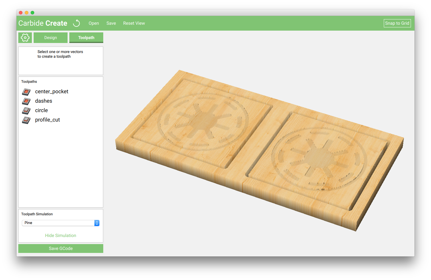
If everything looks good, it’s time export the gcode file and move over to the machine!
Click the ‘Save GCode’ button and save the file someplace you will remember to find it.
To save the design file click the save button at the top of the screen.
The design file is saved a
.c2d file. This is the format that Carbide Create uses to save design and toolpath information for future editing.The gcode file we save is an
.nc file, and is the format that Carbide Motion (our machine control software) will use to actually run the job on the machine.
Machine Setup
With the power to the machine off, move the spindle and gantry out of the way.
Holding down the material - use double sided tape
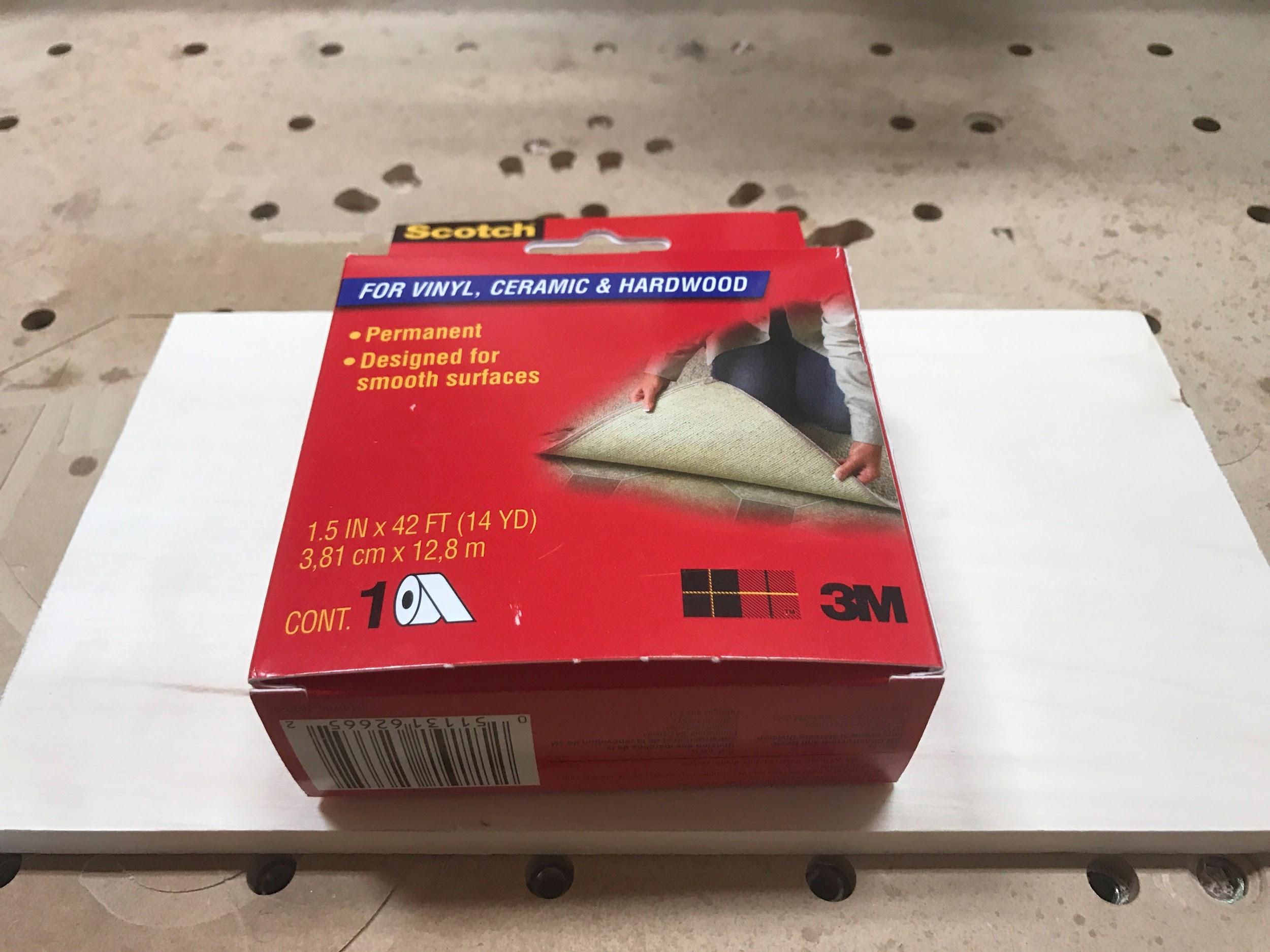
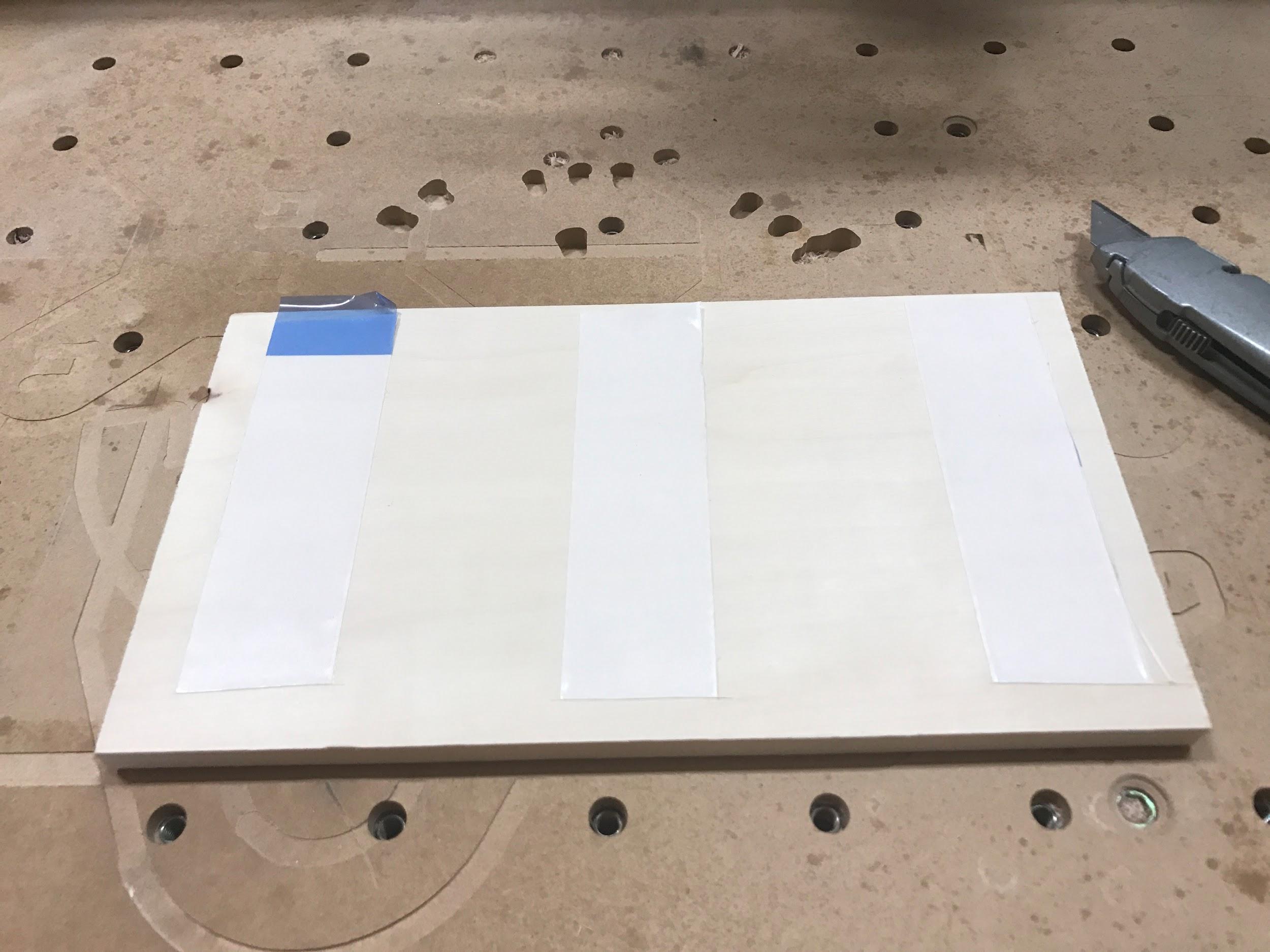
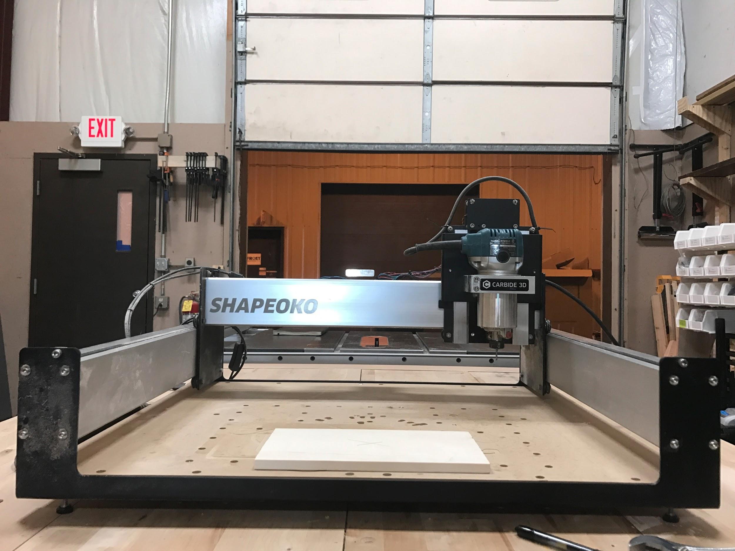
In the front/center of the machine, place the material (in landscape orientation) 2-3 inches from the front lip of the machine.
Using double sided tape, you want to make sure the bottom of the material is clean and free of debris. Make sure the tape is applied evenly and has no major bumps or bubbles.
Tip the material onto the table, making sure to apply even pressure as you push down and that it is close to square with the front of the machine. Press and hold down for a few seconds to ensure the tape has adhered properly to both the material and the table.
Find the center of the material
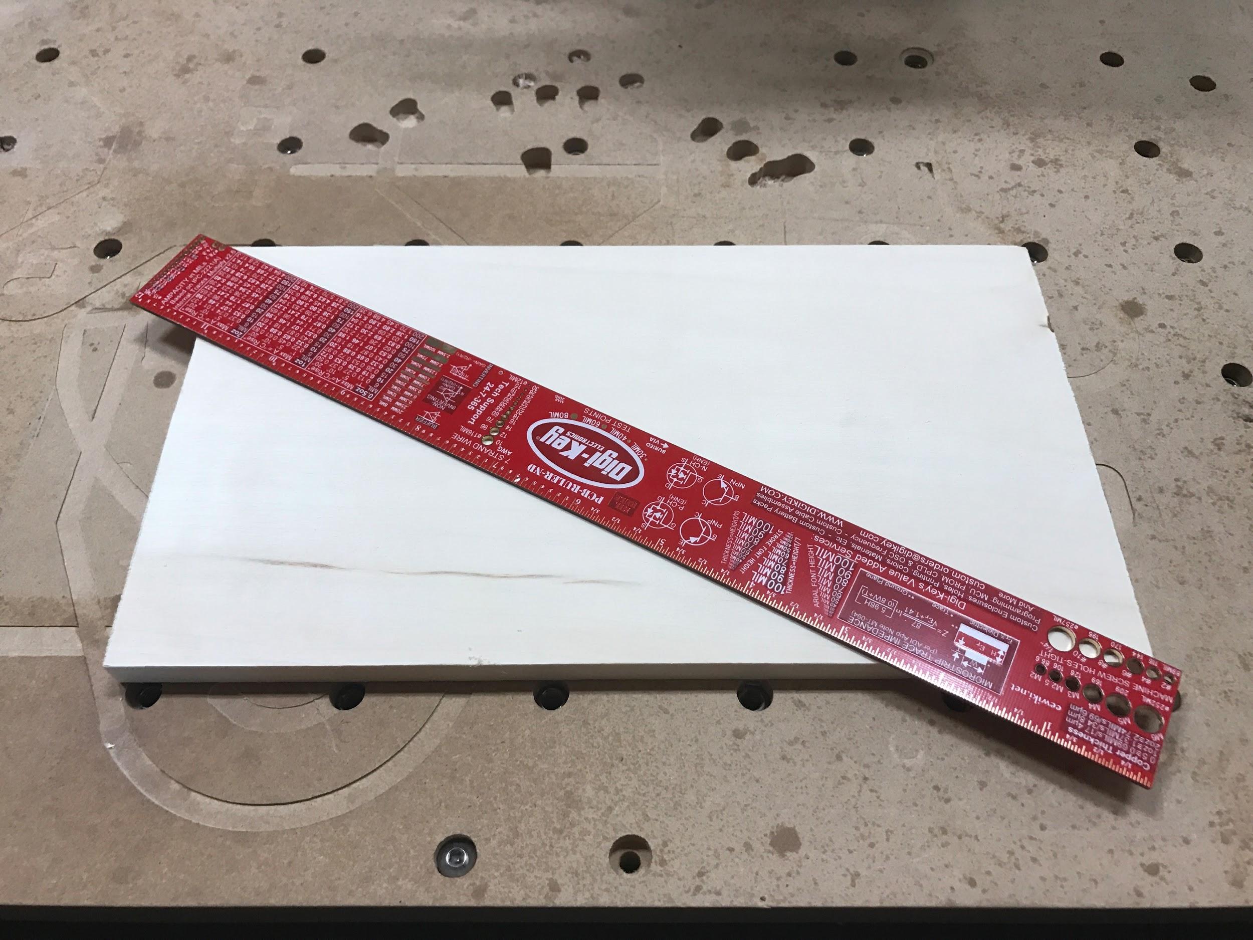
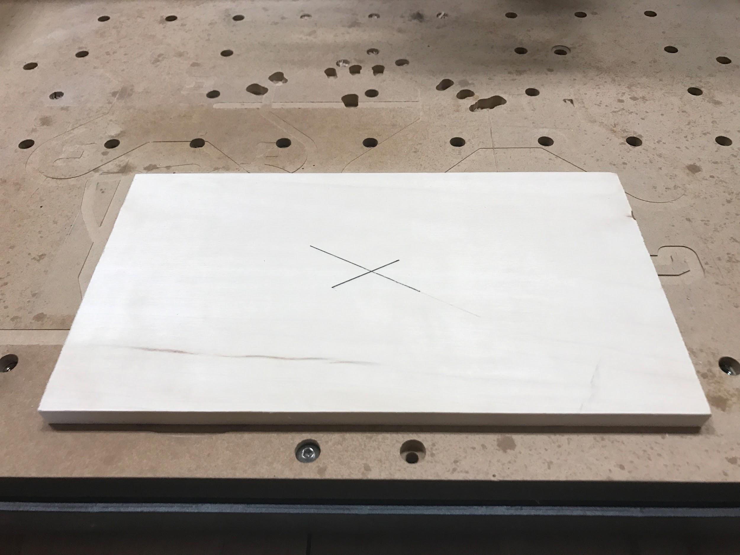
Using a straight edge (like a ruler) mark the center of the material with a pencil or scribe. Do this by laying the straight edge across two corners and marking a line around the center. Then take the straight edge across across the opposite corners and mark another line.
Where these two lines overlap is the center of the material! This is going to be the starting point for our job.
Your material is now setup, and we are ready to load the correct cutter and then connect to the machine!
Connecting to the machine
Plus the USB cable from the machine into your computer. Then plug the machine’s power cord into an appropriate power source, such as a wall outlet.
Turn the power switch on the machine to the ON position. You will hear an audible ‘thump’ when the stepper motors are energized. This means there is power to your machine!
Carbide Motion
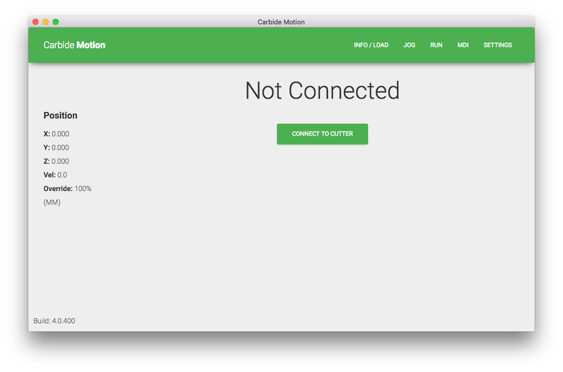
Carbide Motion is the machine control software used to operate your Nomad or Shapeoko CNC machine from Carbide 3D. Think of Carbide Motion as the cockpit for your CNC machine, allowing you to jog, load files, create offsets, and many other features.
When Carbide Motion opens, you’ll be asked to connect to the machine. Simply press the CONNECT TO CUTTER button, and Carbide Motion will connect to the machine.
Once connected, your machine will need to be homed. This gives us a common starting point to move our machine from.
Homing the Machine
Click the JOG button on the top menu. Carbide Motion will ask you to begin the homing sequence by clicking the button.
Once you click the button, the homing process will begin. Your machine will end up in the back right corner., just like the image below.
Clearing previous offsets (fresh start)
Moving to job zero
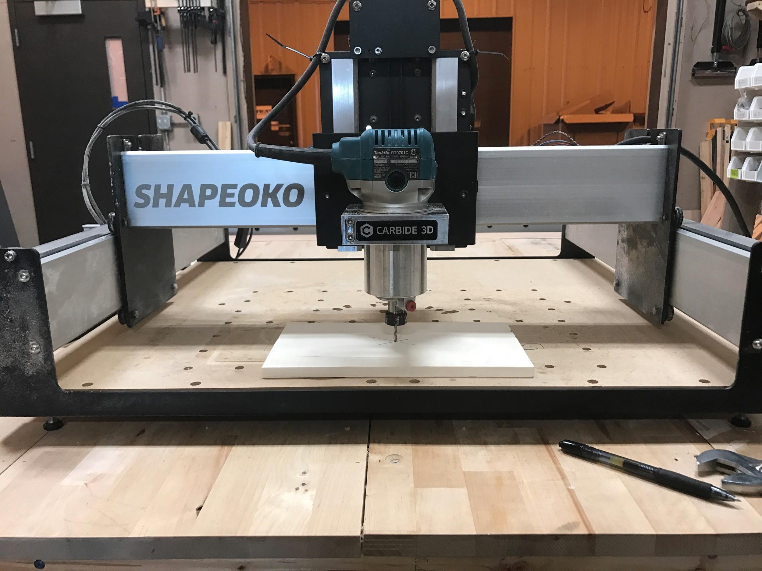
This is the part the messes up a lot of first time CNC users. After you have homed the machine, you then need to jog the machine to where the job is actually going to begin!
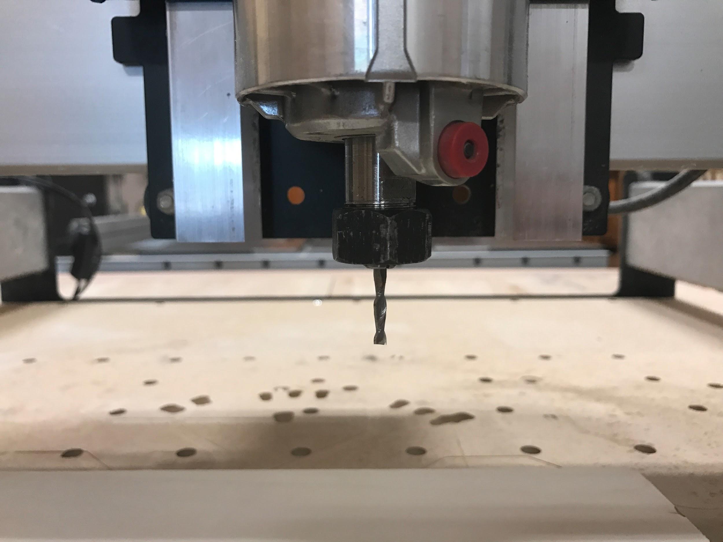
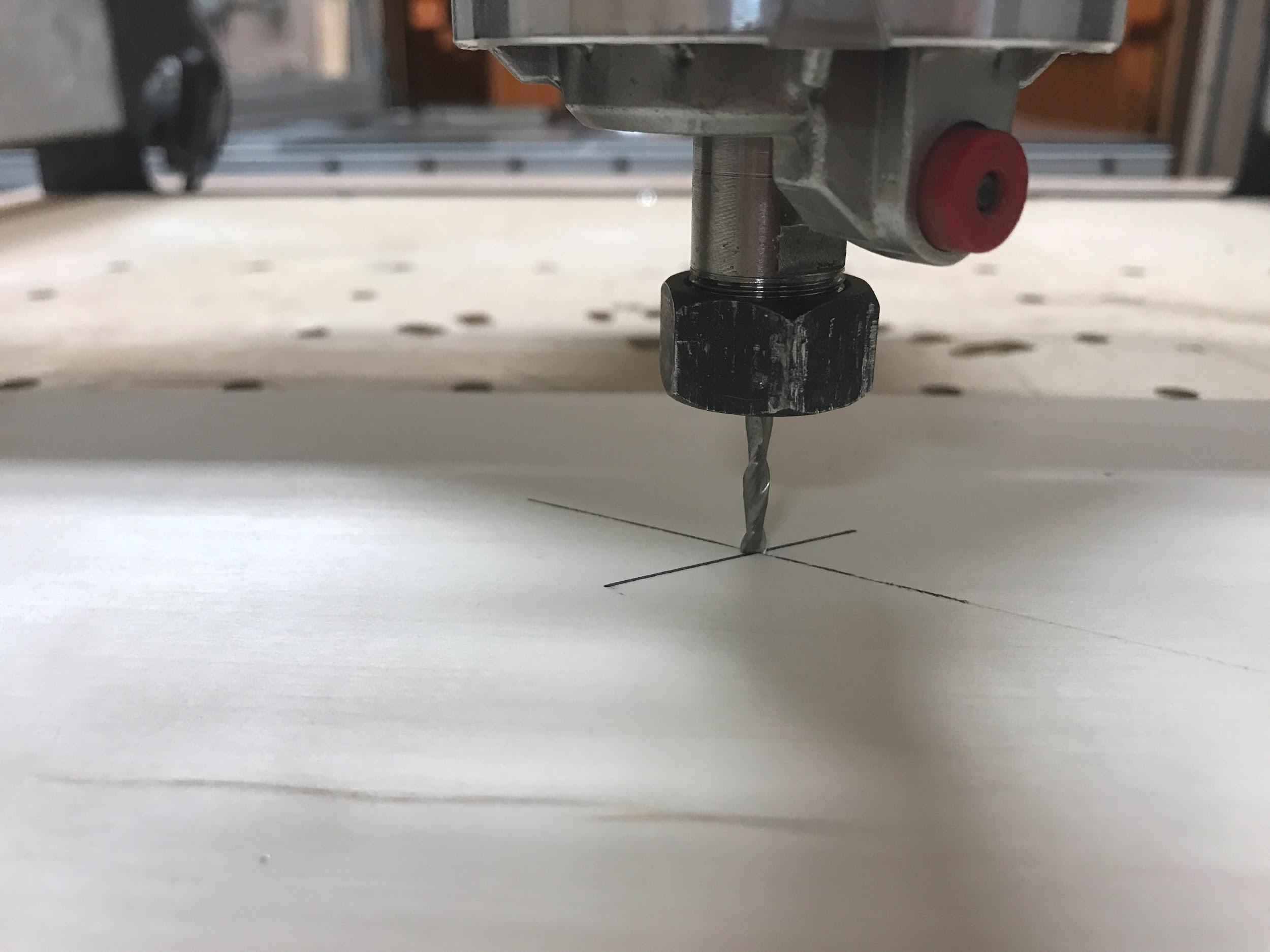
Jog the machine so the cutter is exactly on the ‘X’ we made earlier in the middle of our material.
Once your machine is positioned correctly, you need to click the ‘zero all’ button in Carbide Create.
Clicking the ‘zero all’ button tells the machine THIS IS WHERE THE JOB SHOULD START FROM.
Exit the jog screen, and then load the file we saved from Carbide Create earlier.
After the file is loaded, click the ‘Run’ button in the top menu in Carbide Create. Now is the moment of truth!
Click ‘Start’ - when this happens, the machine will move up 1/2″ from the material. Then Carbide Motion will pause, and ask you to make sure the correct cutter is loaded into the machine. This is your cue to turn on the spindle!
Now, if everything looks correct, click the OK button, and your job will begin!
Begin Job
Main Pocket
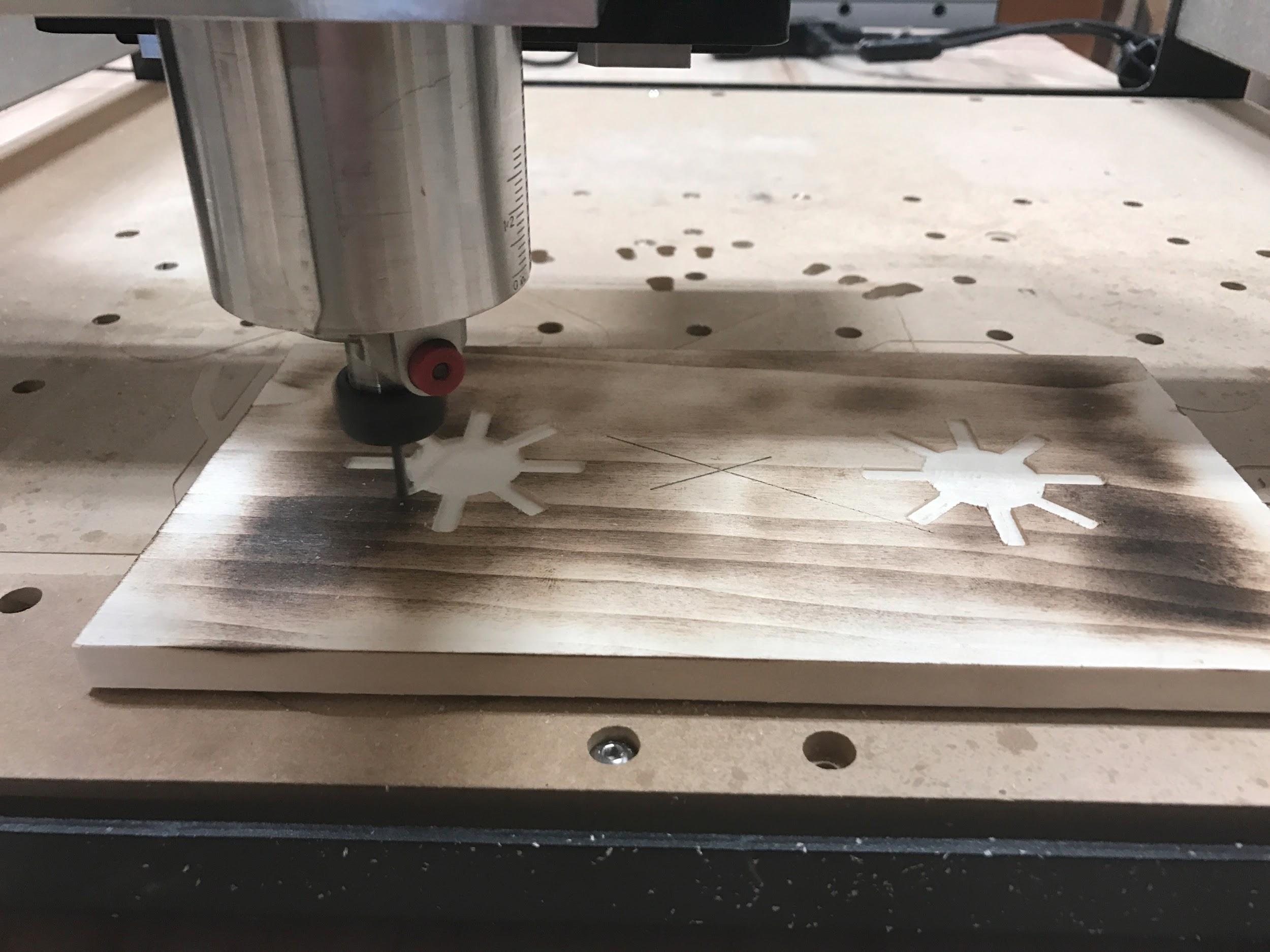
The job will begin by performing the first operation we defined in Carbide Create. This was the main pocket for the center feature.
Dashed Border
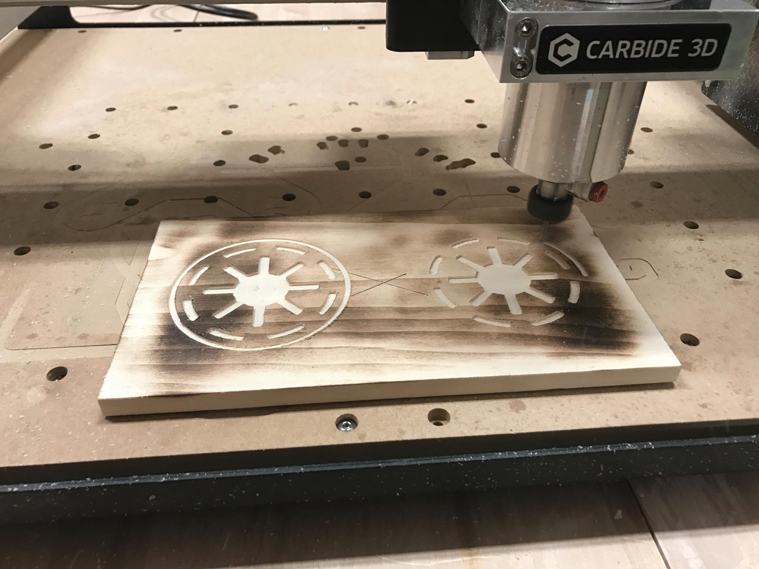
After the center pockets have been routed, the second operation of making the dashed circular border will begin. That will be followed by the 3rd operation, creating the circular engraved border.
Profile Cut
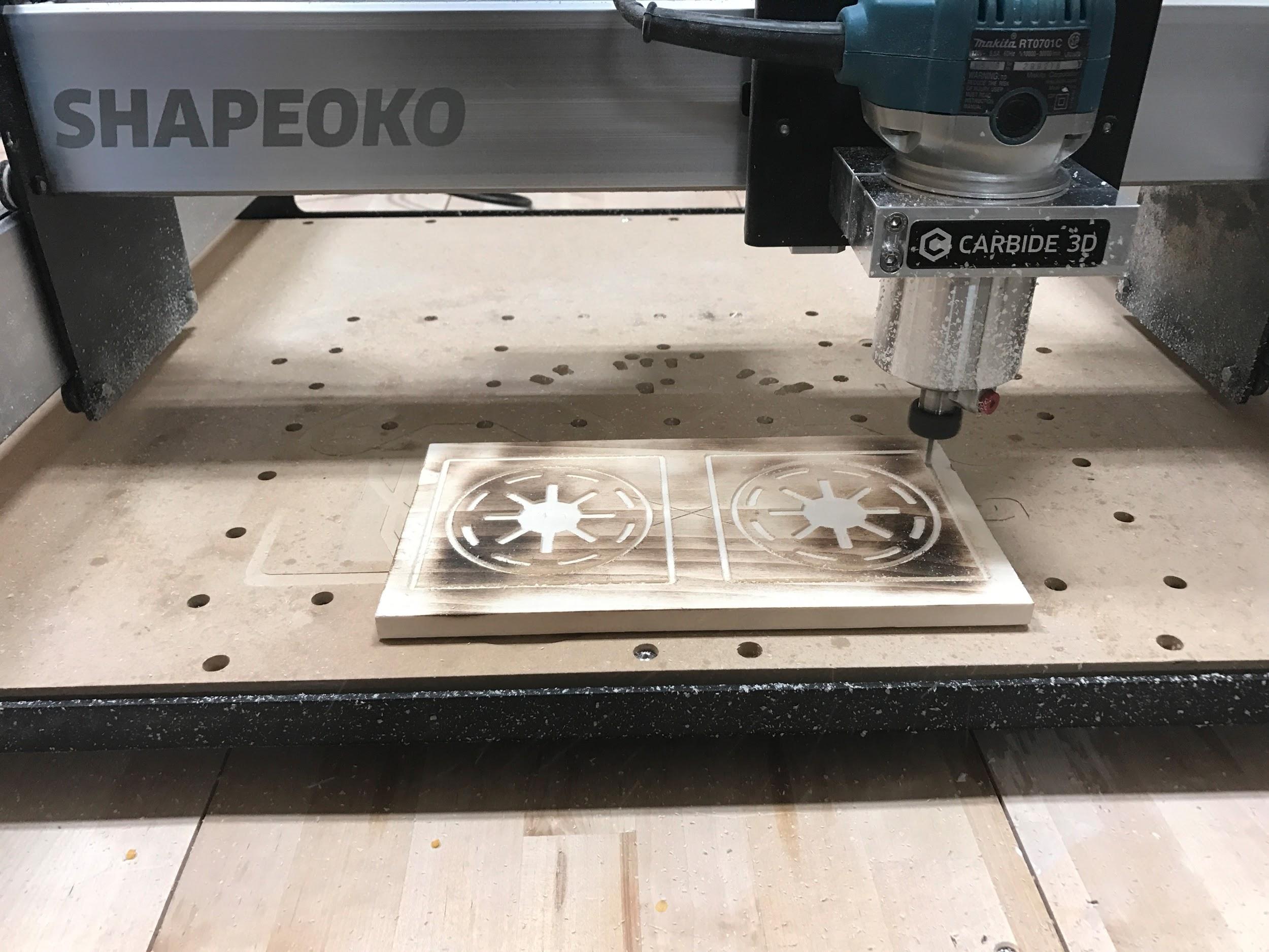
The final operation is the profile cut. This is where your coasters will actually be cut out from the main piece of material.
Take note here that we defined the cutting depth to 1/16″. This means that each ‘lap’ the cutter makes around the material, the bit will be cutting 1/16″ deeper with each pass. If your material is 1/2″ thick, then a total of 8 laps will be required to cut the design free from the material.
Finishing
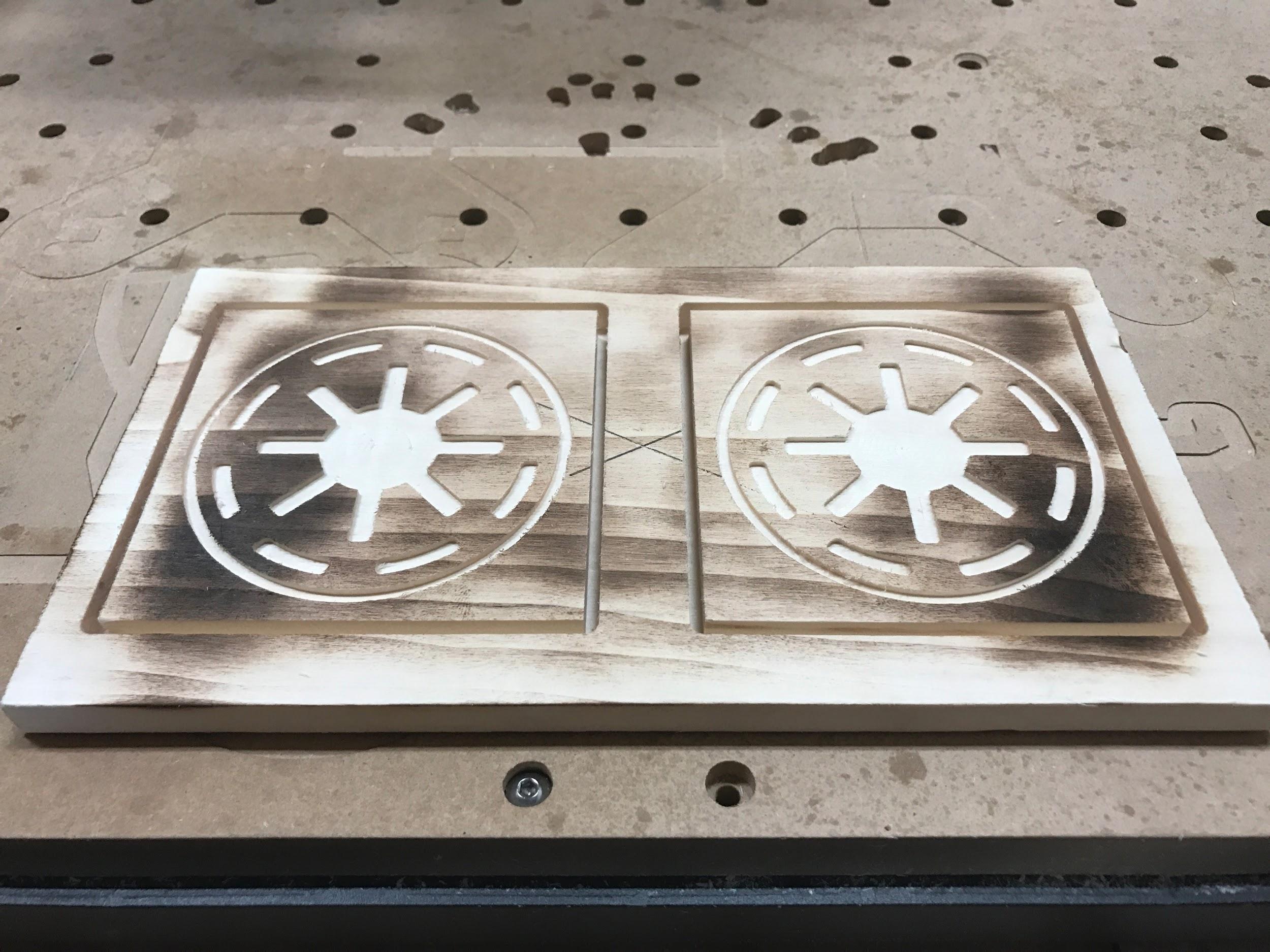
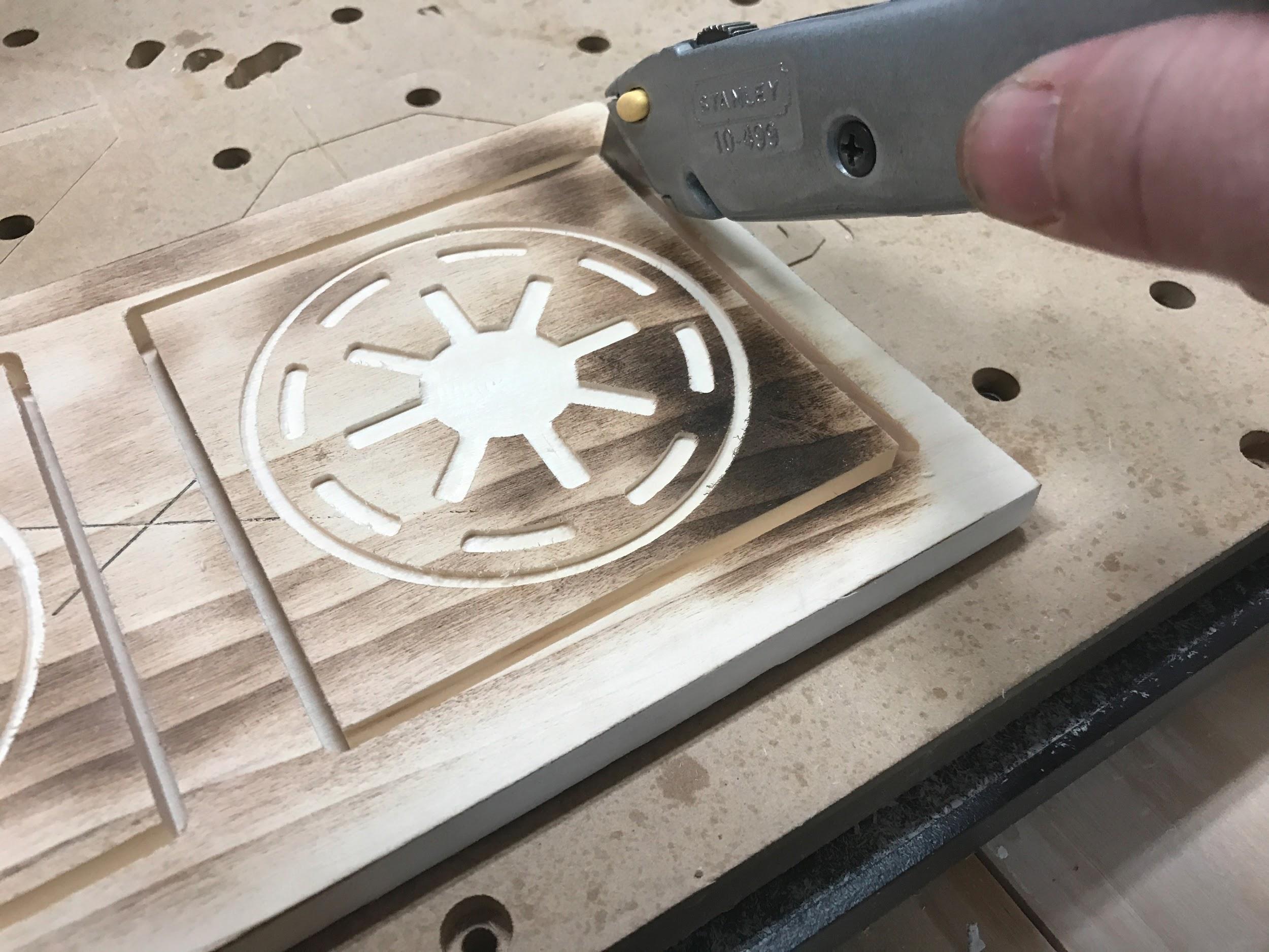
After the final operation is completed, it’s time to begin the finishing process. Remove the coasters from the table. It might be easier to remove the waste material first. A sharp utility knife can come in handy to cut away any thin material that may be left.
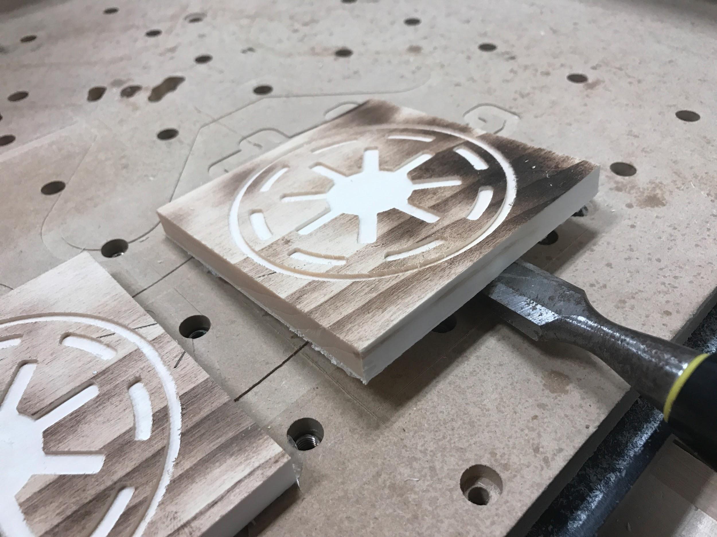
Using a screwdriver, or chisel to pry the pieces from the table may be required.
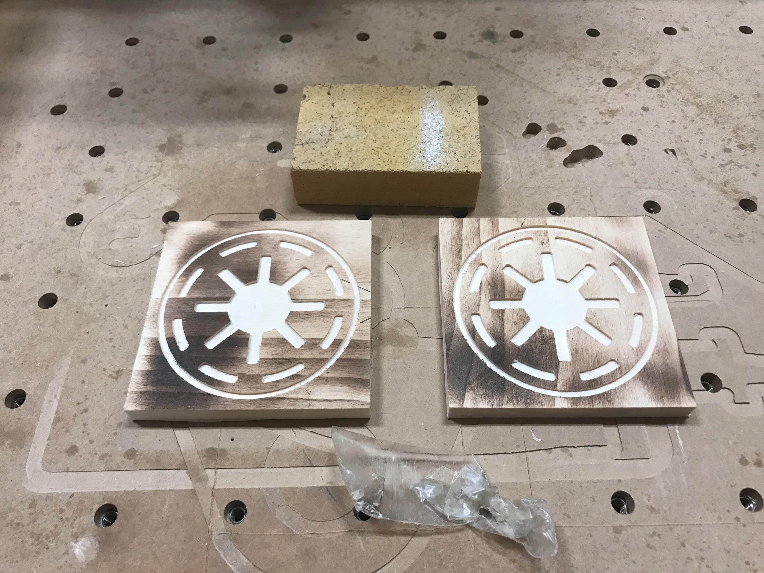
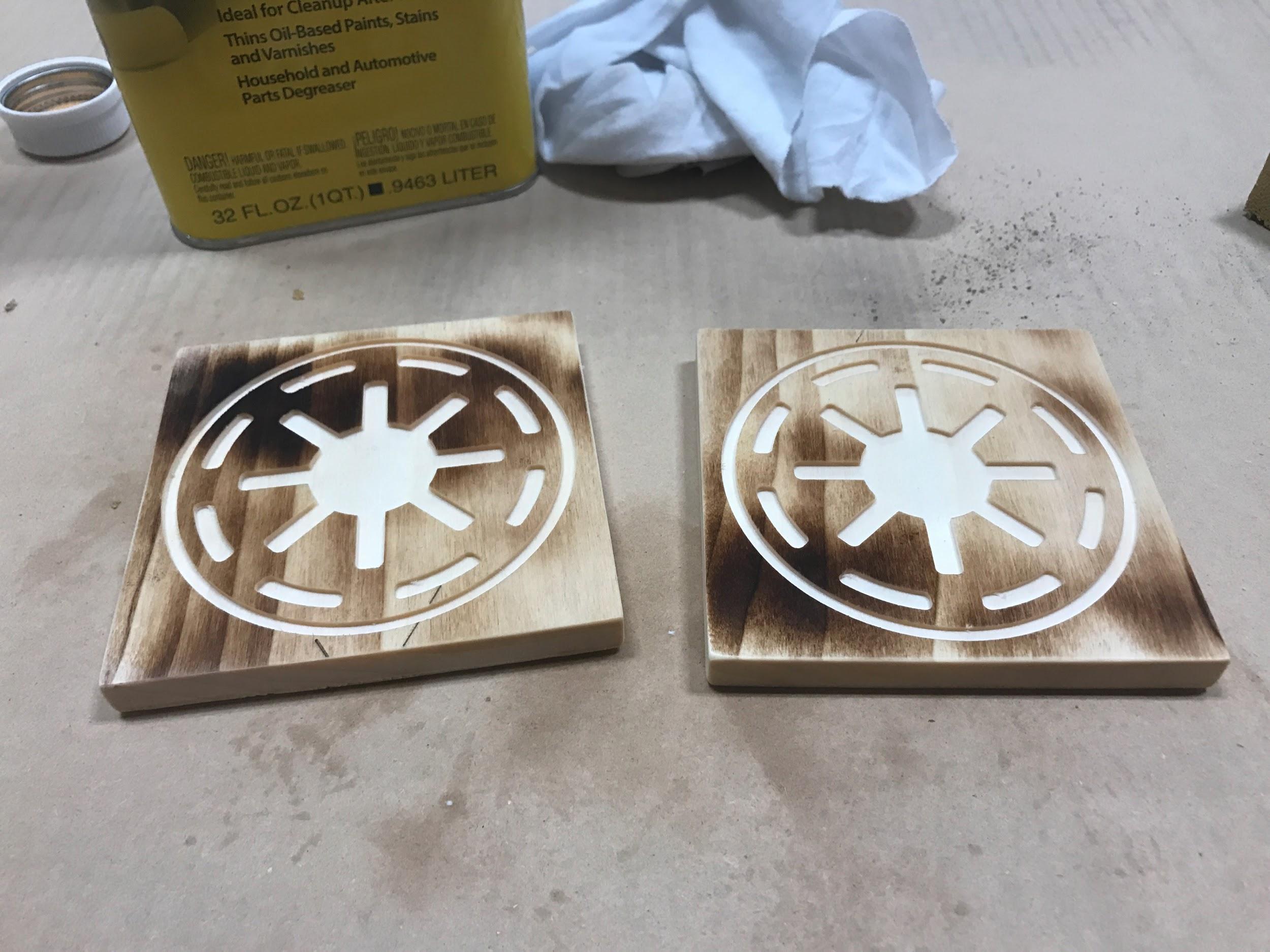
Remove the tape from the back of the material. Don’t worry too much about little pieces of tape, if you wipe the parts down with mineral spirits, the tape will wipe away as well.
Using 220 grit sandpaper or sanding block, sand the edges of the part and lightly go over the top to knock down any burrs or edges that may have been left behind from cutting.
After the parts have been sanded, wipe them down again with mineral spirits to clean the dust off, be sure to get into all of the nooks and crannies with a rag dampened with the mineral spirits. You really want to make sure the part is very clean before proceeding.
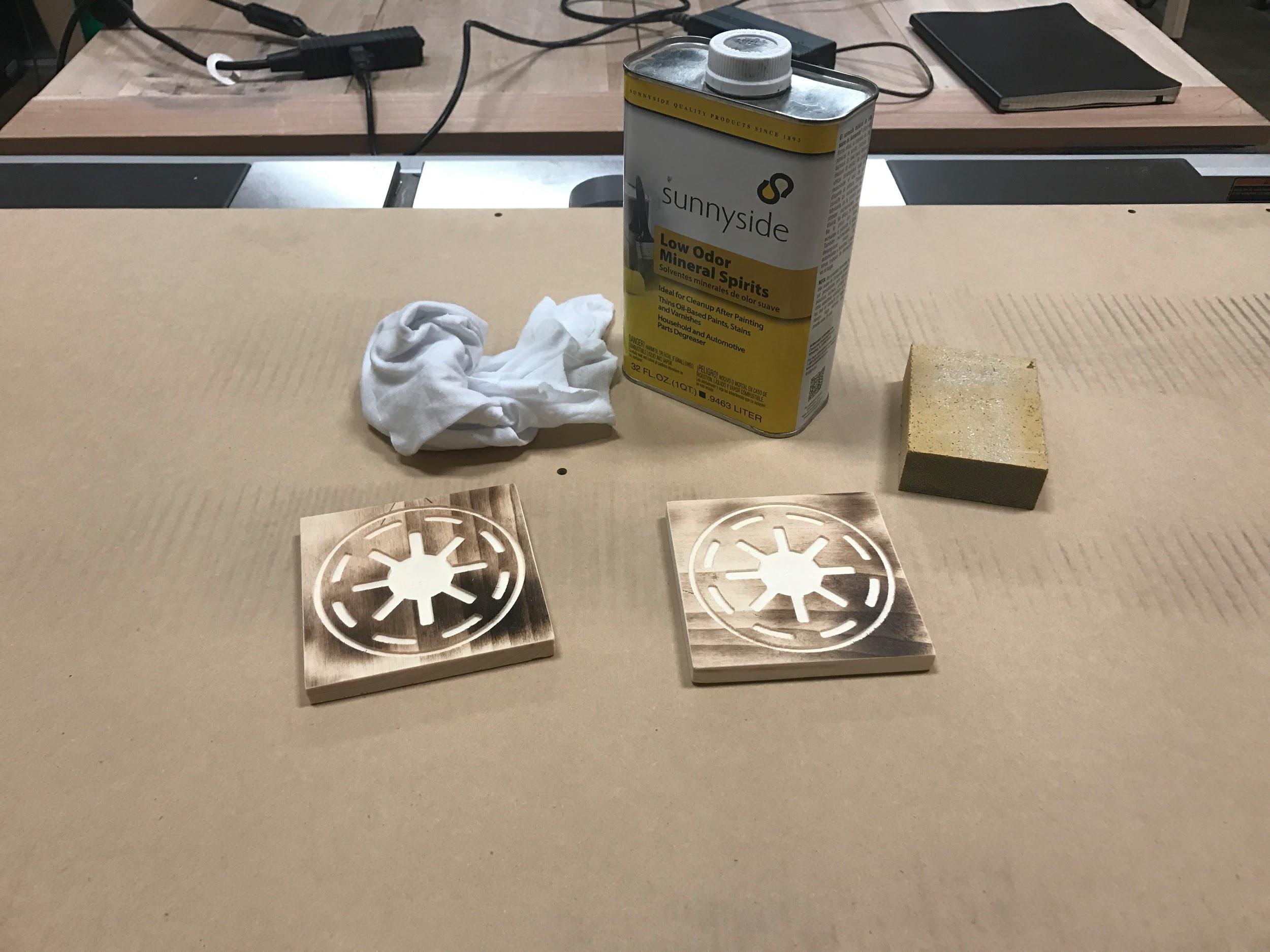
You should notice the parts looking very good, with just a quick cleanup like this!
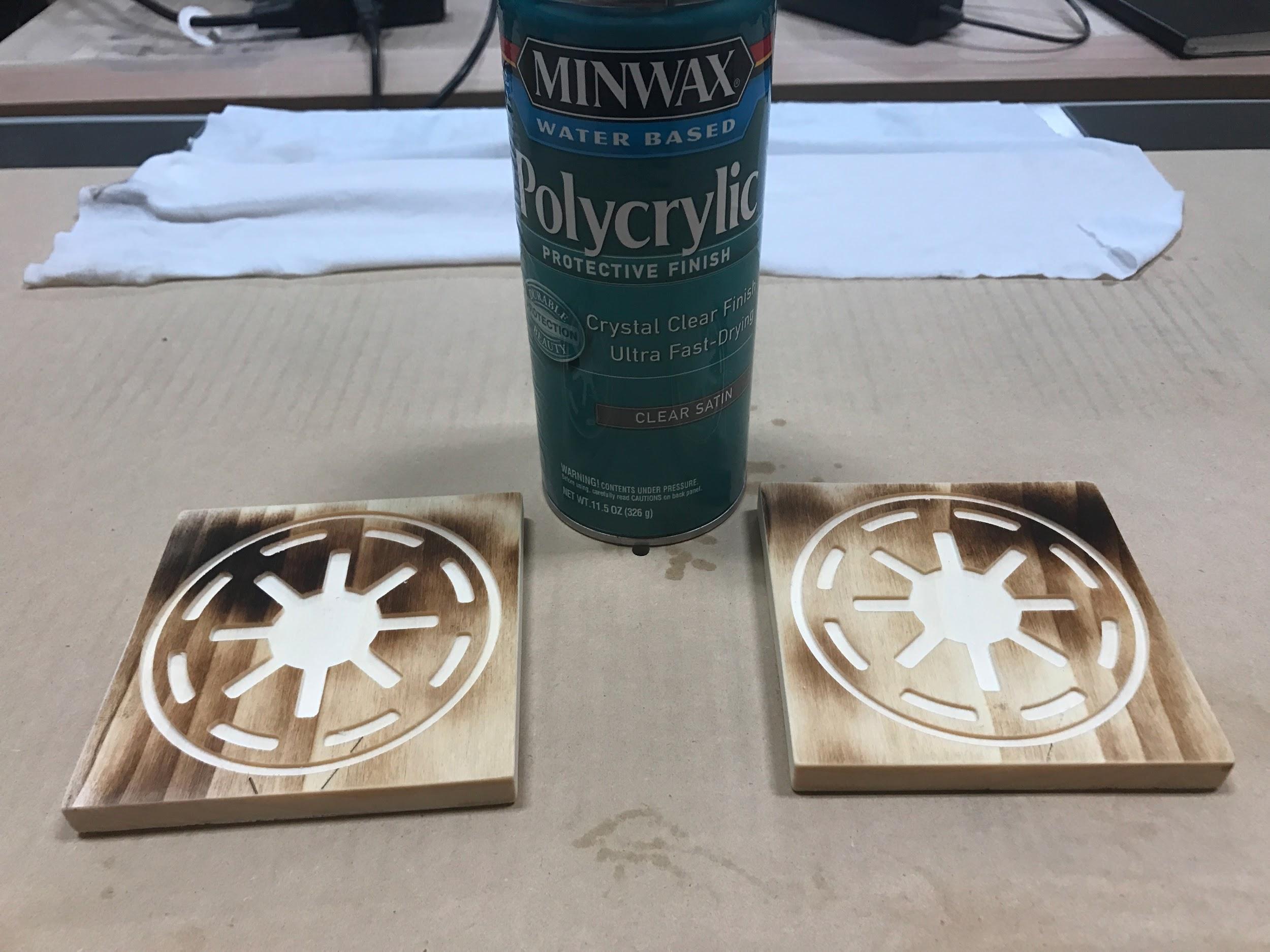
After the parts have been cleaned up and wiped down, you should finish them with some sort of coating to protect against water stains. I’m using Minwax Polycrylic ULTRA fast drying spray polyurethane. Follow the instructions for whatever you choose.
Final
With the parts designed, cut, sanded and finished, you have successfully completed your first actual job!
We learned how to use Carbide Create, how to export our G-Code files, how to use Carbide Motion, and we even learned a little about finishing.