Tool Changes
The most comprehensive tutorial you will ever find about homing, job zero, and creating a repeatable offset with Carbide Motion.
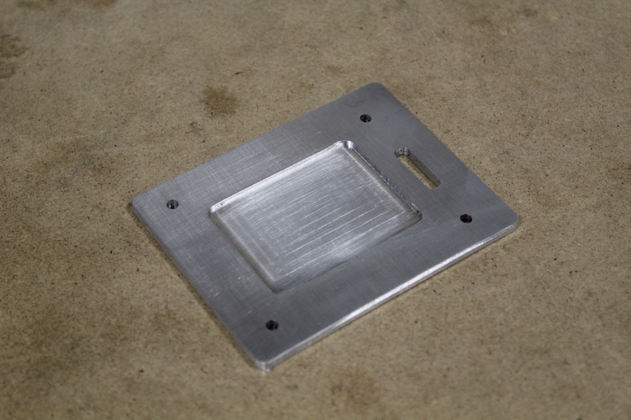 (Finished part using two different tools)
After you learn how to use your machine for basics jobs, you will inevitably wonder how to use multiple tools to create a single part.
Sometimes you’ll want multiple tools to speed things up. For instance, using a larger tool to do a ‘roughing’ pass, and a smaller tool to come through and finish up the details.
Other times you’ll need to use multiple size tools in order to create the features you need. For instance, you can’t drill a 1/8″ hole with a 1/4″ cutter. But if the rest of the job could use a 1/4″ cutter, you could do a tool change just to make the 1/8″ holes.
Point is, there are a variety of reasons you might want to change tools. This article is going to teach you how. Follow along.
Overview
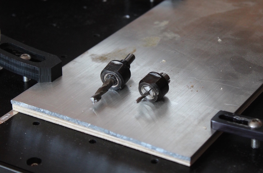
(1/4″ Square Endmill on left, 1/8″ square endmill on right)
For this job we’re going to use two different end mills:
- 1/4″ Square End Mill
- 1/8″ Square End Mill.
Note: the two endmills have different shank sizes as well as cutting diameters. This requires us to use two different size collets. The 1/4″ endmill is using the 1/4″ collet that is included with the Dewalt Router, the 1/8″ endmill is using the 1/8″ precision collet from the Carbide 3D shop.
Job Setup
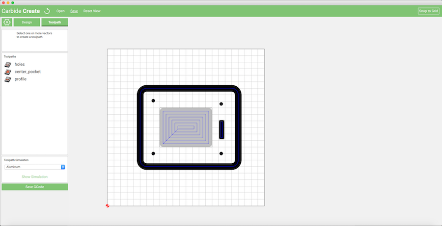 (2D view of job from Carbide Create)
The job consists of 2 operations (or ‘ops’, as they say in the biz). To do this correctly, we’re going to export these 2 operations as separate G-Code files. This is a good habit to get into and will provide us with more flexibility down the road.
First Operation
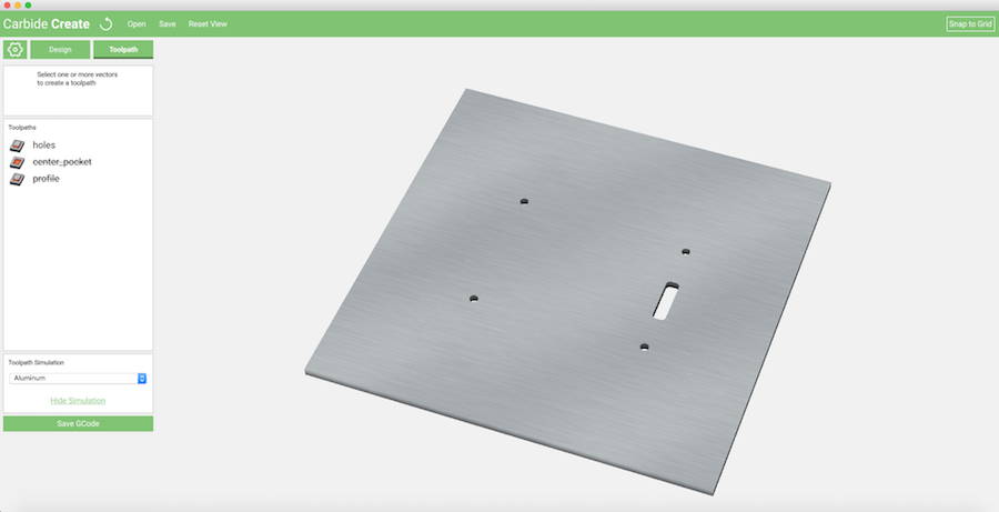 (Showing the 3D preview of the first operation with Carbide Create)
The first op is using the 1/8″ endmill to machine 4 slightly larger than 1/8″ holes (Carbide Create does not drill, so a hole must be at least 10% larger in diameter than the endmill used to machine it), and to create a 3/16″ wide slot down the right side. We are using the 1/8″ endmill because this is the maximum size cutter we could use to create these features.
Second Operation
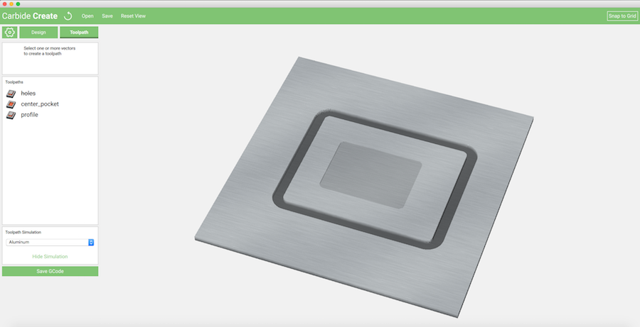 (Showing the 3D preview of second operation with Carbide Create)
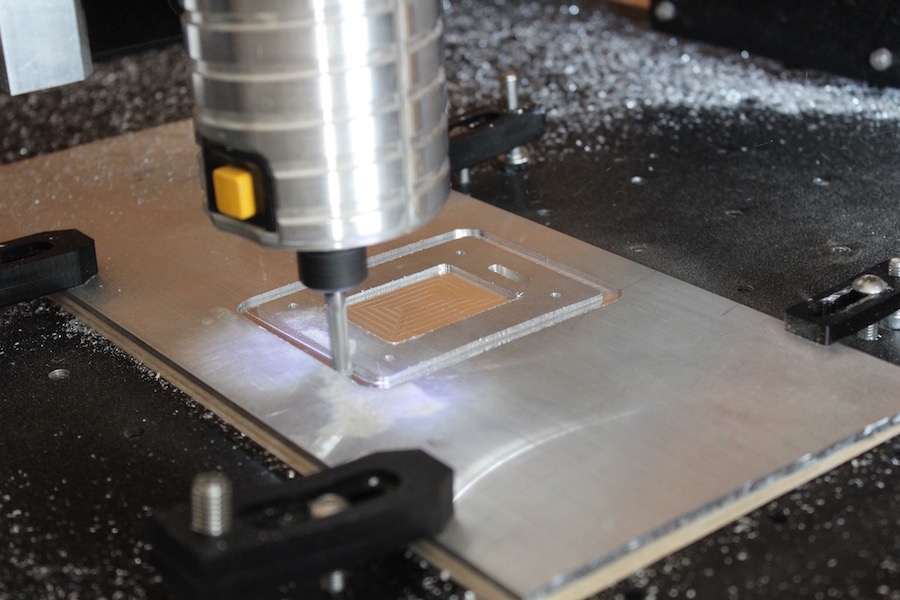
The second op is using the 1/4″ endmill to create a large pocket in the middle of the part, then to cut out the profile of the part. We are using the 1/4″ endmill to speed up the time it takes to create the large pocket in the middle of the part.
Exporting the G-Code
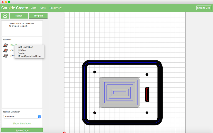
We will export the 1/8″ cutter G-Code first. To begin, right click (or ctl+click) on the 1/4″ toolpaths (pocket, profile) and select disable. This will put a strikethrough across their toolpaths names, alerting you they are no longer active.
With the 1/4″ toolpaths disabled, click the green ‘save GCode’ button at the bottom of the screen. We named our file ‘stand_op1_125’. The ‘125’ portion of the filename indicates that gcode uses a 1/8″ (0.125”) cutter.
Once the first op is exported, go back to the toolpath list and enable the 1/4″ cutter toolpaths that were previously disabled. Once that is completed, disable the 1/8″ toolpath (holes). Export the G-Code again.
We named the second file ‘stand_op2_250’, again using the 250 to indicate we should use a 1/4″ (0.250”) cutter. Note the machine controller doesn’t care about the file name, we put these details in so we remember what is needed.
With your G-Code now saved, it’s time to move to the machine!
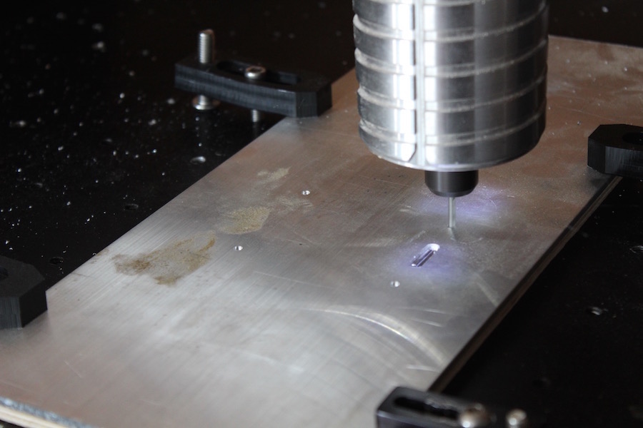
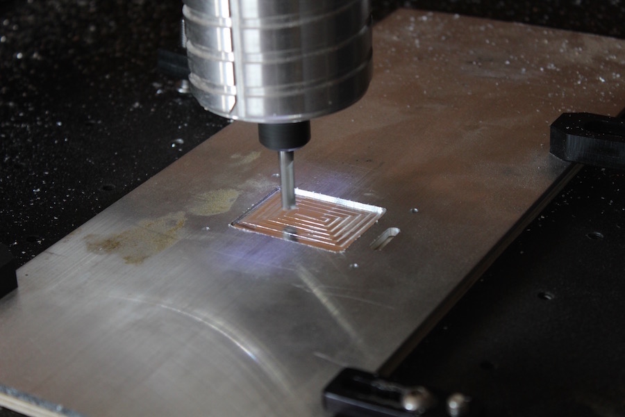
Material setup.
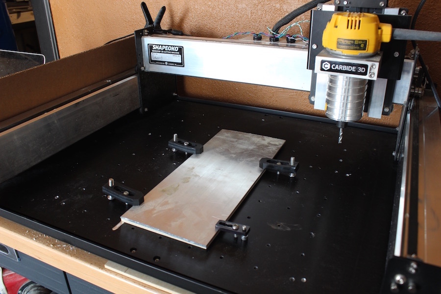
The material we are using is 1/8″ thick 6061 aluminum. The stock piece is roughly 6″ wide and 18″ long.
We setup the material in Carbide Create to be 6″ × 6″ × 1/8″. Although the material is bigger, we are only going to be using a portion of the stock.
There is a piece of 1/8″ wood between the aluminum and the table. This is because the cutting tool will be going all the way through the material. To prevent gouging our beautiful aluminum threaded table, we use the wood as a sacrificial layer.
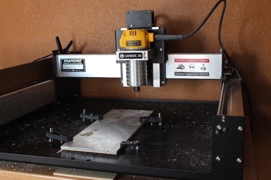
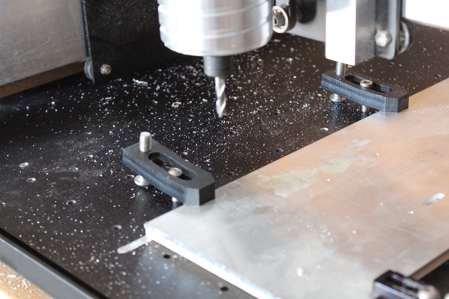
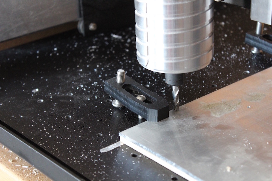
The material is held down at 4 points around its perimeter. It’s very important, especially with harder material to hold down your stock with an adequate amount of force. The last thing you want is for your material to break loose during the job. It’s both dangerous (flying objects!) and frustrating.
Once you are happy with the way the material is being held down, it’s time to load up Carbide Motion and connect to the machine.
Carbide Motion
Once you are connected to Carbide Motion, you will be placed in the info screen. From here, click the jog button to begin the homing process.
After jog is clicked, you’ll be asked to home the machine. Do so now.
Homing
After the machine is homed, the gantry and carriage will be in the back right position of the table. This is home. Put a doormat there (or if you are nerdy call it 127.0.0.1). Either way, just remember the back right corner is home.
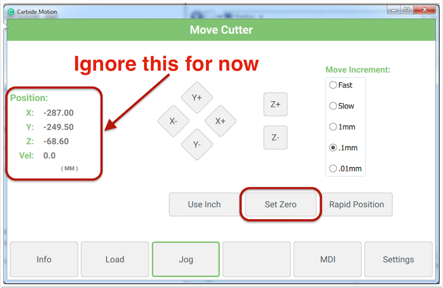
Regardless of what the ‘Position’ reads, click the ‘Set Zero’ button. Because we just ran a homing cycle, we know the machine is in its home position.
Clear Existing Offset
Because we are starting a new job, we need to clear any existing offsets.
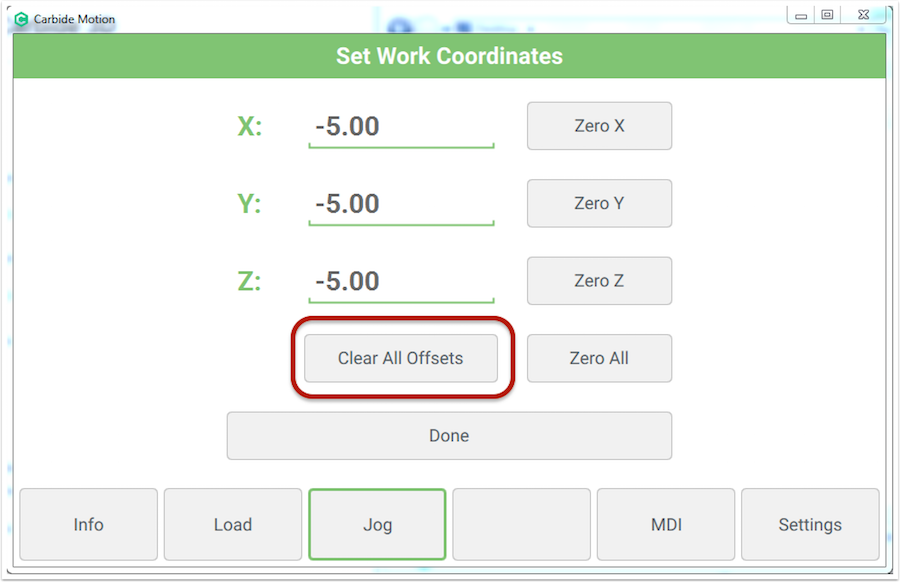
Click the ‘Clear All Offsets’ button.
You’ll notice that all 3 of the axis values change to -5.00 (mm).
This is because after each axis touched its home switch, it ‘backed off’ 5mm, so as not to be sitting on the switch (which would trigger an error). So the home position is actually 5mm away from the switch’s contact point. That’s not too important, dont get hung up on it. Just know that when you click ‘home’ the machine will always move to this exact position.
Job Zero
What we need to do now, is move the machine to where the job is going to start.
This is where people usually get confused with homing. You think, I just homed the machine, can’t I run the job from here? No. You cannot run the job from here!
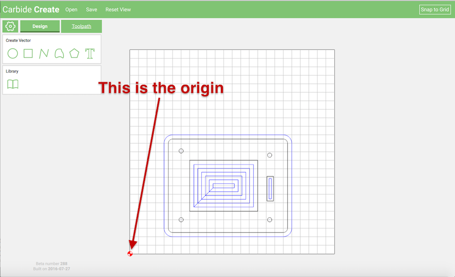
Why? Because when you setup the job in Carbide Create, more than likely, the ‘origin’ was in the bottom left hand corner. The origin is where the tool is going to start the job.
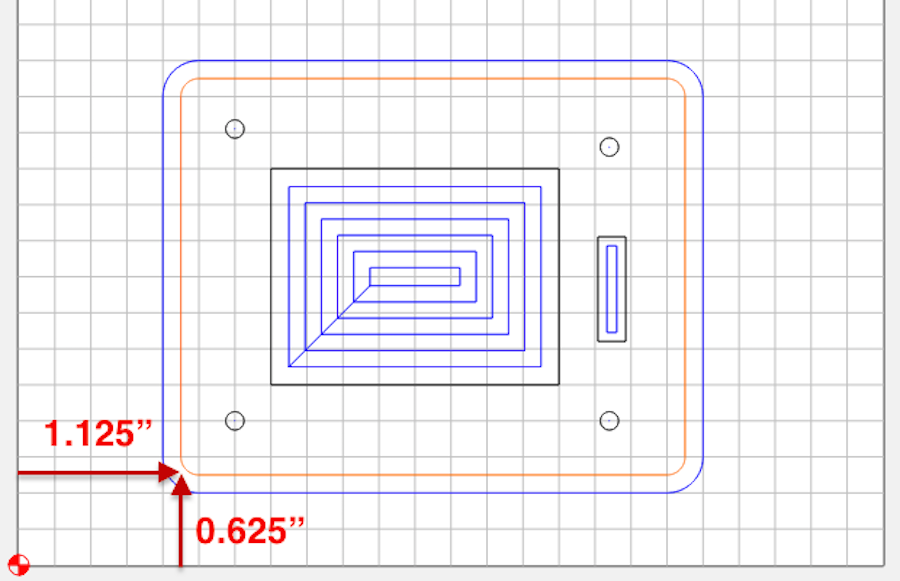
To compound the confusion, in our example (and in many projects you’ll run into), the origin is in the bottom left, and the design (where the tool will actual cut) is not exactly on the origin. In fact, the design is set away from the origin in both the X and Y axis.
- Design begins at 1.125″ from origin in X-axis direction
- Design begins at 0.625″ from origin in Y-axis direction
This means that when the job actually starts, the cutter is going to move 1.125″ in the X direction (this would be moving from left to right), and 0.625″ in the Y direction (this would be moving front to back). So if the machine were in the back right corner (at the home position), and you tried to run this job, it would immediately try to move 1.125″ in the X direction and 0.625″ in the Y direction — that would cause it to slam into the back right corner!
Why is job zero important?
You need to remember that every job you make will begin from the origin (0,0,0). So where ever your machine thinks 0,0,0 is, that is where the job will begin from.
From that zero point, the cutter could then move even further away from zero in order to begin cutting the job, as shown in the example.
There are 2 things at work here:
- Home — This is a fixed location on your machine where the carriages park after sending the ‘home’ command.
- Job Zero — This is where you move your machine to in order to begin the job
Moving to the origin
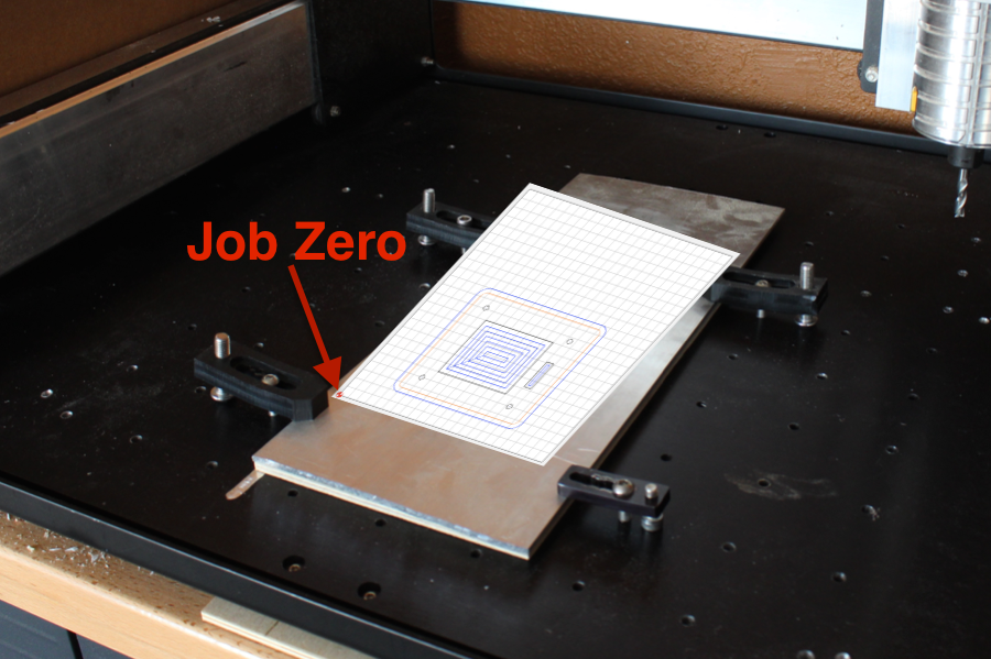
Imagine the design is laid out on your material. We can take the same view from Carbide Create, and overlay it on the material. Wherever the origin is located, that is where you need to jog the machine!
Typically, you would think about how large your job is, then setup your material and clamps accordingly, just as I did in this job. The material setup in Carbide Create was set to 6″ × 6″. This was because the material is 6″ wide and I set 6″ between the clamps. If I lay the design out on the material, I know the whole thing will fit, and we wont run into clearance issues.
Use the arrow buttons in Carbide Motion to jog your machine to the job zero location. When you get close to the point where you want X/Y to begin, it’s time to touch off.
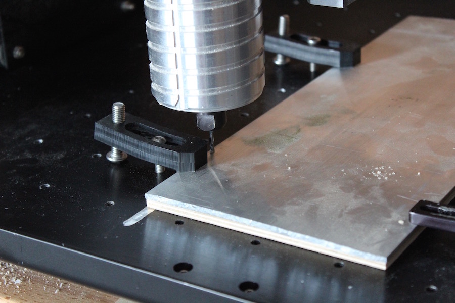
Touching Off
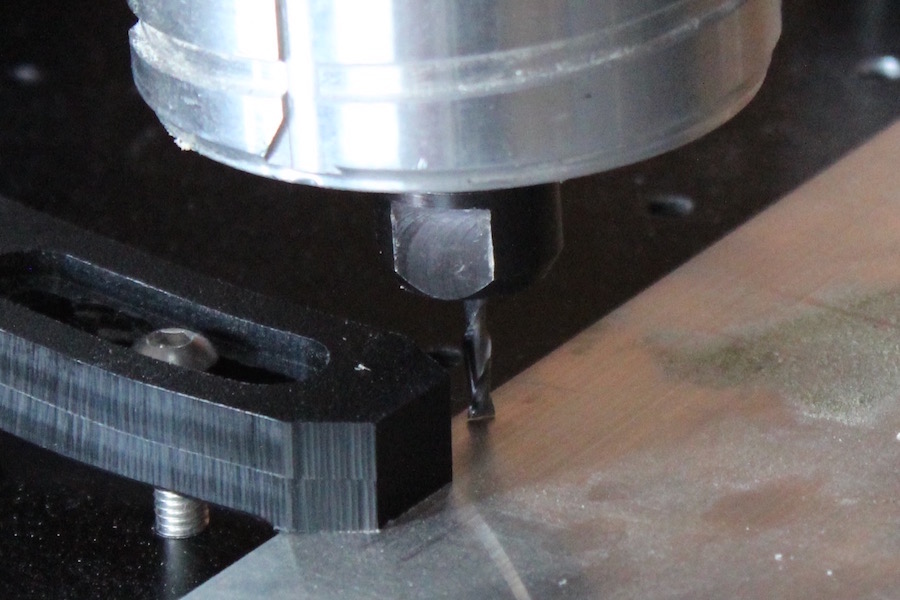
This is important. You’re going to see this term everywhere. What does touching off mean?
Touching off is setting the zero point on your Z-axis. It can mean other things, for instance, you could touch-off on an edge. But by and large, it means setting your z-axis zero point.
Remember, as you are moving your Z-axis down, you can also adjust your X and Y axis. As the bit moves closer to the material, it’s easier to see how close you are to where you want to start the job.
To touch off:
- Lower the Z-axis down towards the material
- As the bit gets closer, slow down (or decrease the increment) you are using to jog.
- Insert a piece of standard paper between the bit and where it will touch the material
- Begin simultaneously moving the paper back and forth, across the top of the workpiece, and lowering the bit
- When the bit catches the paper, and prevents you from moving it back and forth, stop jogging the Z-axis down!
- This is the ZERO point for your Z-axis.
Creating an Offset
We have now jogged our machine away from the home position, and to where we want the job to actually begin! Congratulations. This is a big step.
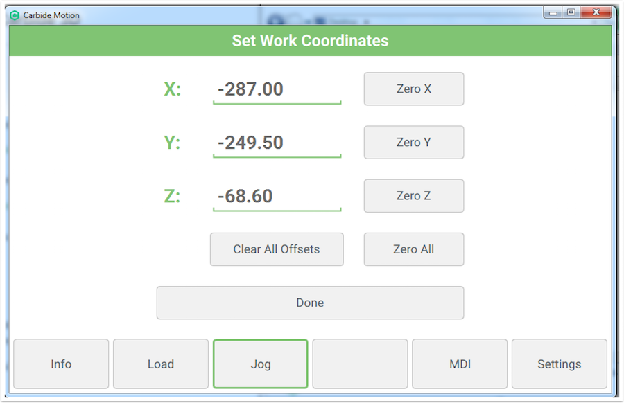
Click the ‘Set Zero’ button in the Carbide Motion Jog Screen
If you look at the coordinates for X, Y, and Z.
- X = −287.00
- Y = −249.50
- Z = −68.60
On the surface, these may not make sense. But, think of them in relation to the home position. These coordinates shown are the distances from each axis away from the home position.
If you were to write those coordinates down, then shut off the machine. Unplug it, move the gantry around, do whatever. Then turn the machine back on, and re-connect with Carbide Motion, you could get back to EXACTLY this position. Every time.
But, you don’t need to write those coordinates down. Carbide Motion makes this easy for you. More on this in a minute.
Back to the machine: Now that the machine is positioned exactly where we want it to be for the job, we need to zero all 3 of the axis: X, Y, and Z.
- Click ‘Set Zero’ button in the Carbide Motion Jog screen
- Click ‘Zero All’ to set the X, Y, and Z-axis to 0.00
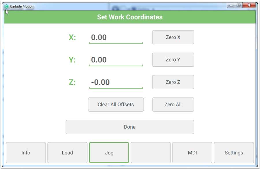
Setting zero here tells the machine that this is where we want to start the job. From this very point, all G-Code will run relative to this point.
Click ‘Done’ to exit this screen.
Operation 1
Now that the machine is homed, and we have created our offset. It’s time to load the G-Code file.
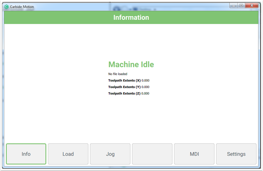
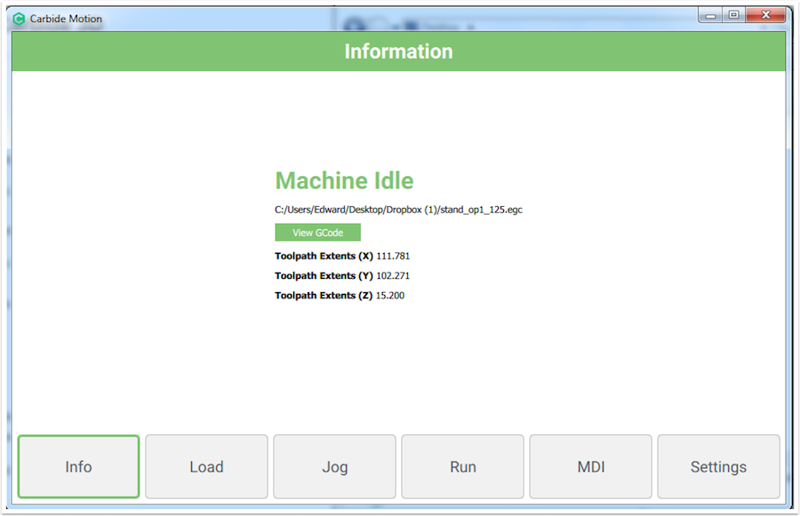
After you have browsed for, and loaded the egc file, Carbide Motion will send you to the ‘info’ screen. From here it’s important to note a few features.
- The extents of the job are shown. If you’re looking for a ballpark idea that you have loaded the correct file, the extents are a good place to look. These show you the total amount of travel in all axis.
- Clicking the green ‘View GCode’ button will display the raw gcode in txt form. From this screen you can copy the plain text G-Code to your clipboard, from which you can do whatever you’d like.
Running Operation 1
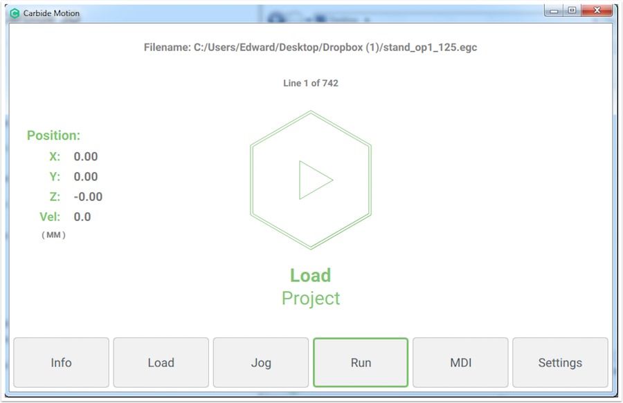
With the job loaded, it’s time to run this operation! Click the run button, and Carbide Motion will move you to the ‘run’ screen. To begin the job, click the play button in the middle of the screen.
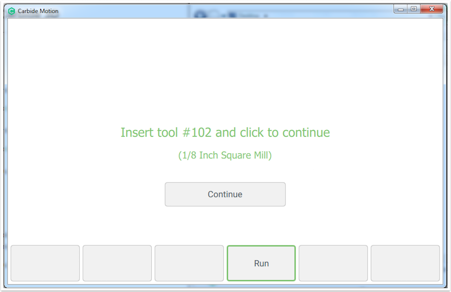
Immediately after pressing the start button (small triangle in middle of screen), your router will move up to the safe height defined from Carbide Create (the default is 12mm). After the tool has moved up, Carbide Motion will prompt to insert the correct tool.
When the correct tool is in place:
- Turn on the Router
- Press the ‘Continue’ Button
Operation 1, continued
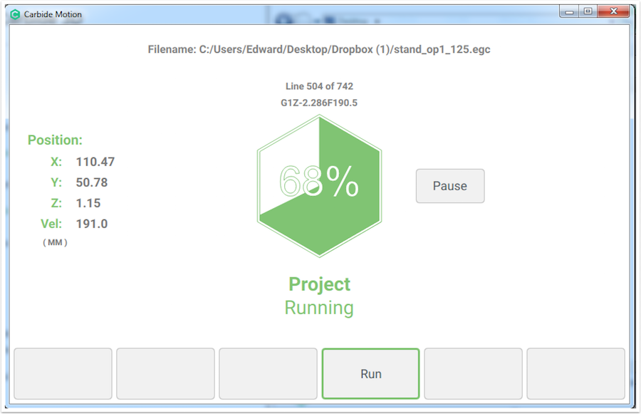
Your operation will continue to run. As it does, Carbide Motion will update you on the progress of your job. Indicating the percentage of the job completed, and what line of G-Code the job is currently running.
Finishing Operation 1
When this operation finished, the machine will raise to the safe height (12mm by default in Carbide Create), and then move itself to the back center position of your machine.
At this point, it is safe to turn the router off, and to turn off the machine. You can close Carbide Motion and shut the power down to your machine if you’d like.
With the power off, simply drag the gantry to the front of the machine so you have enough room to change the tool.
After the tool has been changed (be sure to tighten the collet nut with a wrench!), turn the power to the CNC back on, and re-connect Carbide Motion.
Once Carbide Motion is connected to the machine, it’s time to really take advantage of the features we have built in.
Returning to offset
Click the ‘Jog’ button in Carbide Motion. This will force the homing routine to begin.
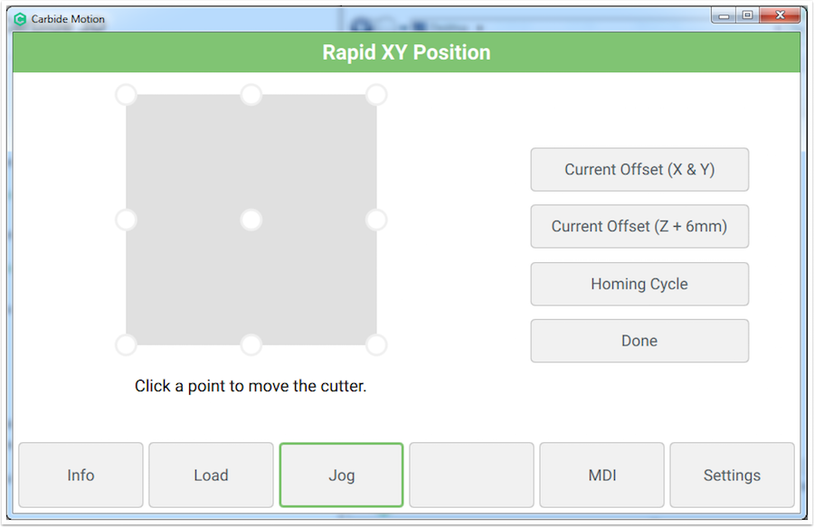
After the homing routine has completed, press the ‘Rapid Position’ button from the jog menu. You’ll be presented with a screen similar to what is shown above.
Before we can begin operation 2, we need to get back to the same exact position we defined for operation 1 (the same job zero location). Luckily, Carbide Motion remembers that information for us.
Just press the ‘Current Offset (X & Y)’ button to return the machine to the last offset you created!
It’s important to note here that we just moved the machine back to the exact X and Y coordinates where our first operation was started. However, the Z-axis needs to reset.
Resetting the z-axis
The Z-axis needs to be reset because Carbide Motion doesn’t know how long the tool you inserted for operation 2 is, compared to the tool you used for operation 1.
The Nomad CNC machine that we also designed, actually has a tool probe built in. One of the features it does is to measure the tool, so this step (resetting the Z-axis) does not have to be done
To reset the Z-axis, just touch off again! When you get the cutter to the correct position (a piece of paper’s width from the material), click the ‘Set Zero’ button, and then click ‘Zero Z’.
Done! Now it’s time to load the second operation
Second Operation
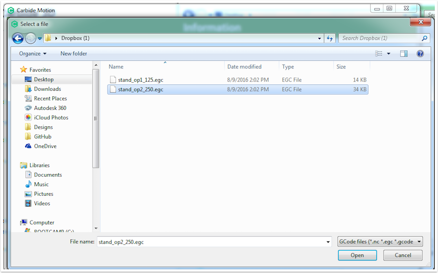
Using the load menu, browse for, locate, and open your second operation G-Code file. Once the file is loaded, click the ‘Run’ menu.
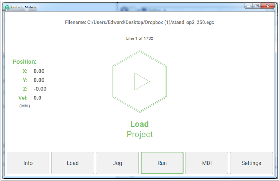
Click the start button, and you will be presented with the Tool Load prompt. Ensure you have the correct tool in place, then turn the router on.
Once the router is on, press the continue button to begin the job!
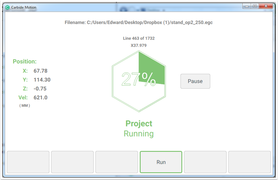
As the operation runs, Carbide Motion will update you with the progress. Showing the percentage completed, and the line number of G-Code it is currently processing.
The pocket operation will run first, followed by the profile operation. Once the profile operation is complete. The job is done, the machine will move to the center-back position, and it will be safe to shut off the router, and disconnect from the machine.
(Finished with a quick pass of Scotch Brite)