Hold Down Clamps
Create Your Own Hold Down Clamps
This is a quick and easy project to make on any size Shapeoko CNC machine.
The instructions below walk you through creating the toolpaths with Carbide Create and setting up the job with Carbide Motion
Download Carbide Create Project (with finished toolpaths) here: Shapeoko Clamps (or as a ZIP archive: Shapeoko-Clamps.zip
If you run into any problems or have questions, please email support@carbide3d.com for assistance.
A few notes about the project:
- This job will be setup to start from the center of the material in the X and Y directions
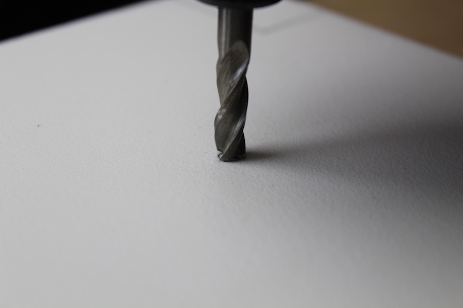
- We used a 1/4″ square end mill (#201 from our store) — The job will take about 8 minutes to complete.
- We used 1/2″ HDPE (6″ × 6″ stock) (McMaster-Carr Link)
Open Carbide Create
Import the Project File
Browse for the shapeoko_clamps.c2d file you downloaded from the top of the page, and click OK once you find it. The file will open on the canvas.
All of the job setup information should be pre-populated with the correct information. Please double check your job setup to make sure the material size and type matches what you'll be using.
Click Job Setup Icon (gear in top left corner)
Set Material Properties
- width: 6″
- height: 6″
- thickness 0.500″
- Stock: Top
- Toolpath Zero: Center
- Material: HDPE (we used black)
- Machine: Shapeoko 3
- Retrack Height: 12mm
- Units: Inches
Click OK
Create Toolpaths
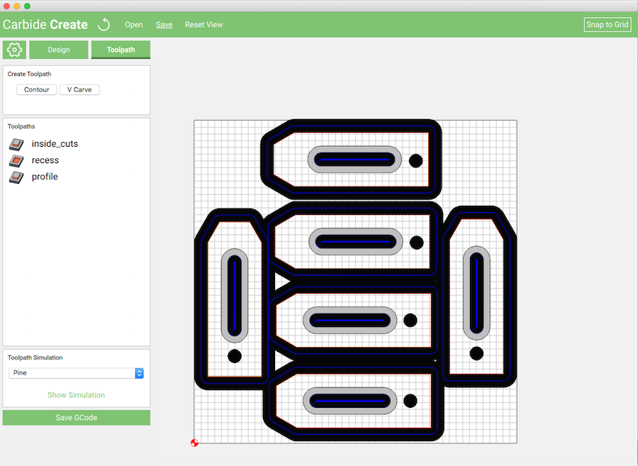
There are 3 operations to create the clamps.
- Full Depth Slot (inside cut)
- Recessed Pocket (recess)
- Profile Cut (profile)
We will be using a 1/4″ square end mill for all of the operations. Be sure the correct tool is selected from the tool drop down menu. Notice that the speeds and feeds will be filled in automatically for you if you check that option (but have been updated to the official feeds and speeds for HDPE, please adjust as necessary). Also note that Carbide Create remembers the last tool you used and defaults to that tool.
Slot
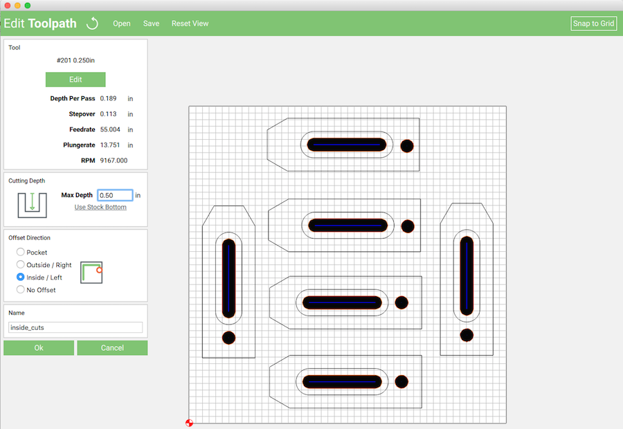
While holding control key, select all of the center oval vectors (the smaller oval) by clicking each one with your mouse. It may be necessary to zoom in to click the correct vector.
In addition to the center ovals, also click the circles at the back of each clamp, these too are inside cuts that are full depth.
Note: The holes were designed to be 6.75mm, which is the drill size for an 8mm tap. If you're going to use threaded inserts you can change the hole size here so the holes are the appropriate size for your inserts.
After all of the vectors have been selected, click ‘Contour’ under the Create Toolpath menu.
These are full depth cuts, set the depth to ‘use stock bottom’, and then select the inside/right Offset direction. Name the operation “inside cut”
Recess
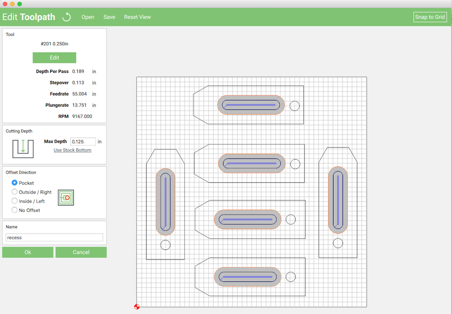
The recess around the slot gives the screw head room to hide below the surface of the clamp.
With the head sunken, it’s less likely you will hit the screw if you accidentally run into the clamp during a job.
Profile Cut
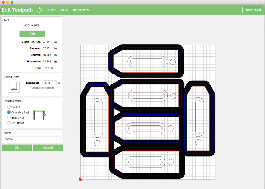
We measured our material at 0.495″ thick. Choosing 0.500″ assured the first operation (inside cuts) made it all the way through the material (by at least .005″).
The profile cut removes material from the outside of your design. In order to cut the parts out from the material, but not have them fly all over your workshop, we are going to use a trick to make sure they stay in place all the way through cutting.
Instead of choosing ‘stock bottom’ for the Depth of Cut, we are going to input 0.490″.
By doing this, the cutter will not go all the way through the material. Instead, you’ll be left with .005″ of material. Sometimes this is called ‘leaving an onion skin’ on the bottom. The onion skin will keep the parts in place, and we can easily remove them during finishing.
A good rule of thumb, especially in plastics such as HDPE, is to leave about .005″ of material for your onion skin, this will take uneveness into account if you material thickness varies a few thou.
3D Preview
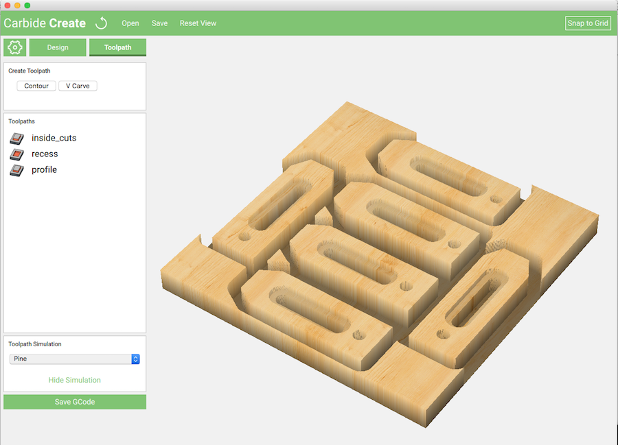
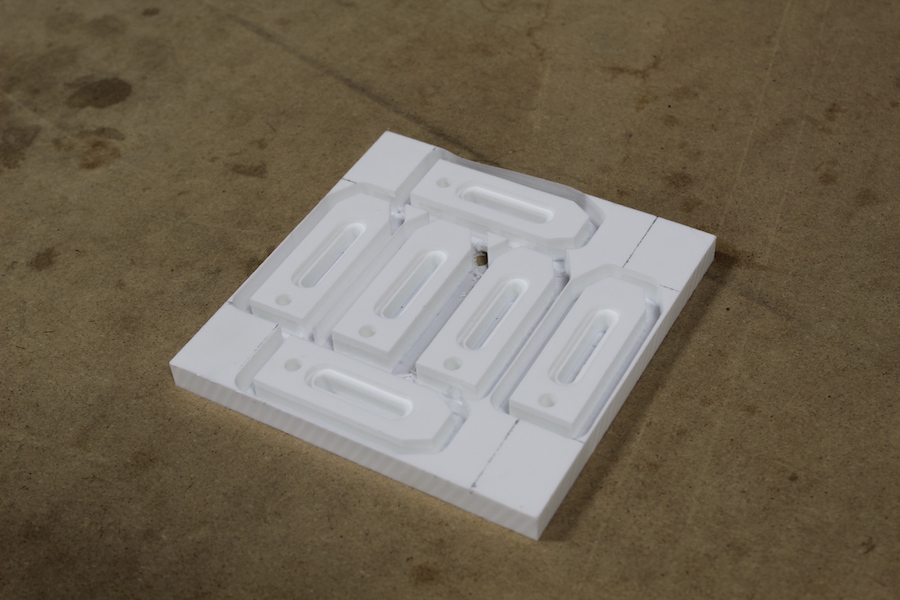
With your toolpaths complete, you can preview what the design will look like after it’s been cut into the material. Under the toolpath simulation heading, click select ‘pine’ for the material, then click ‘show simulation’
Here is a photo of the finished parts, taken from the same angle as the 3D preview. You’ll notice they are identical. So if there is something you’re not seeing, or something that looks off in your preview, it's worth double checking as your parts will more thank likely turn our exactly like the preview.
The 3D preview is full 3D:
- click + drag to rotate
- scroll to zoom in/out
- ctl + click and drag to pan
- Pressing ‘Reset View’ will reset the 3D view
When you're happy with the design, click ‘Save GCode’
Machine Setup.
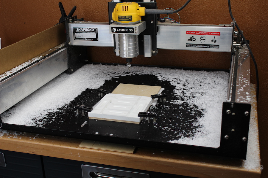
Now that the toolpaths are done and you’re happy with the preview, it's time to setup the material on the machine and actually run the job!
This project may be a little bit of a ‘chicken and the egg’ problem, in the sense that you need clamps to hold the workpiece down, but the project is actually creating the clamps you might need. So, do what you can to hold the material down reliably to the wasteboard.
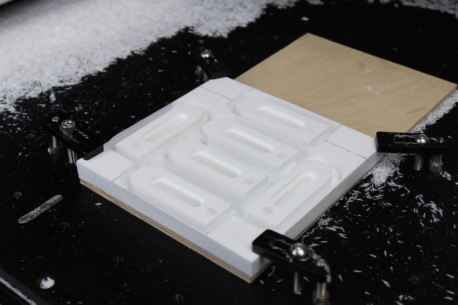
Using a piece of 6″ × 6″ material (1/2″ thick):
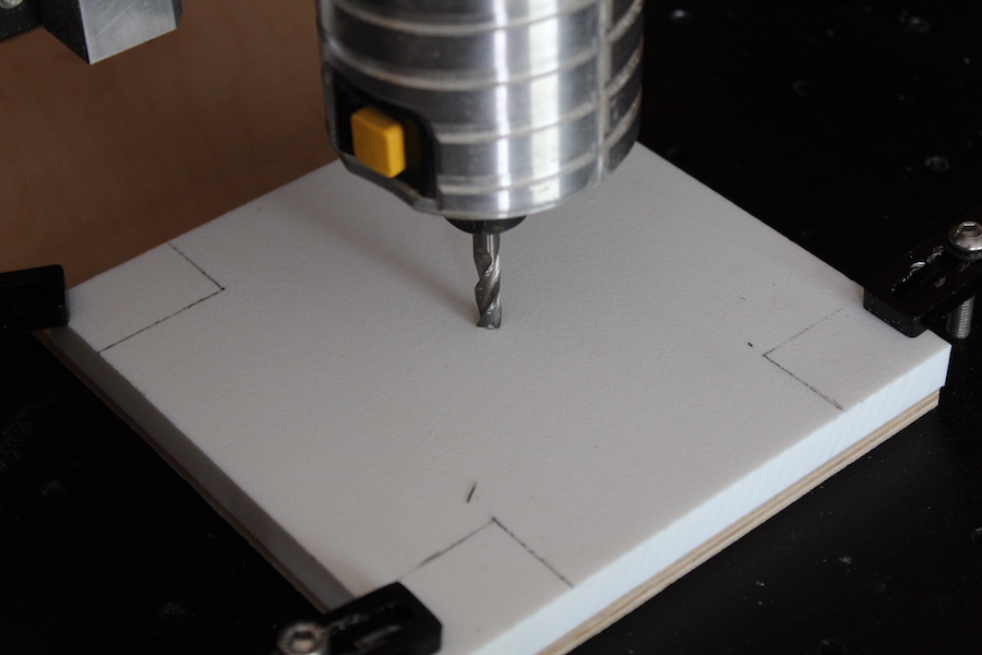
Mark the center of the material with a pen or other utensil. The easiest way to find center is to just draw two diagonal lines across the material, one from each corner. Where the two lines meet is the center.
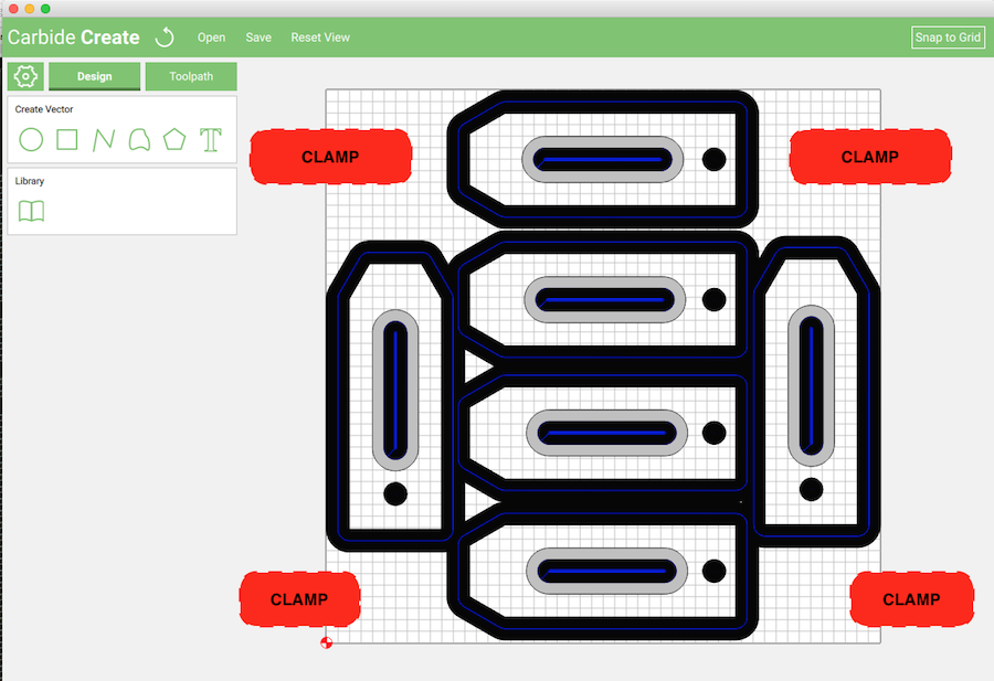
You'll notice in the design, there is no cutting in any of the 4 corners, if you're using clamps to hold down this workpiece, a safe place to put the clamps, so as not to interfere with the toolpaths, are in the corners.
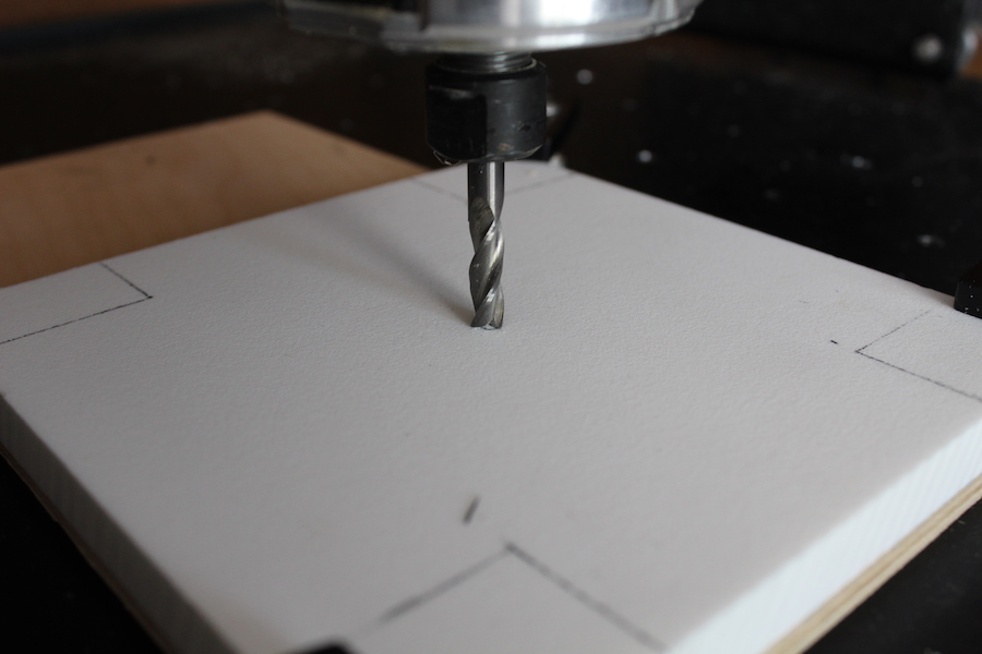
The above image shows the ‘safe’ areas marked with a pen on the material. Dont be afraid to do this on your own piece of material. It's better to spend a little extra time to know for sure that your clamps are not going to interfere with your job!
Job Setup (Machine Controller)
Now that the material is held down securely, before we can run the job, we need to move the machine into the correct position to with Carbide Motion.
If you do not have homing enabled:
- move your machine to the job-zero position (center of material), then turn the power on.
- Open Carbide Motion and Connect to your machine.
- Go to the jog menu and ZERO the X/Y axis.
- Jog the Z-axis down until it’s just touching the material, then zero the Z-axis.
-
Load the .nc file you created with Carbide Create.
- Click Run!
If you have homing enabled
With homing enabled, we need to reference the machine to home, and then create an offset to the job zero location.
- Power on the machine and connect with Carbide Motion.
- Click the jog button to begin the homing cycle.
- After homing, click the rapid position button that moves the cutter closest to your work piece.
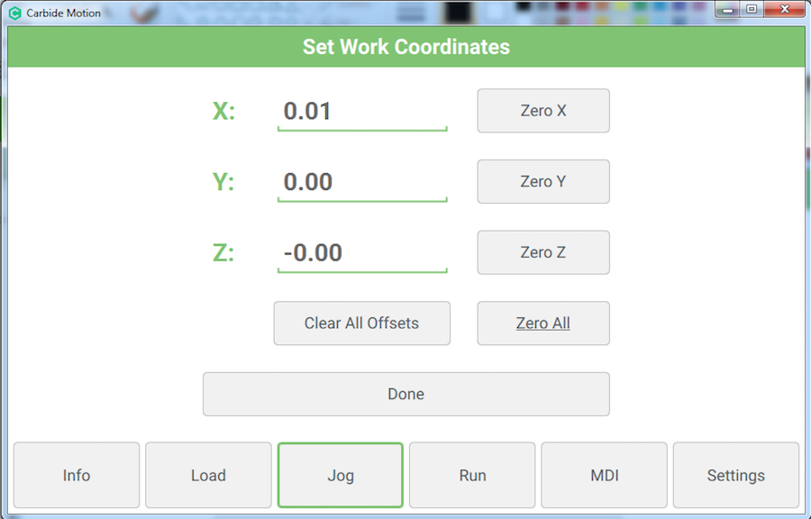
Jog to job zero
Once the machine has moved to the rapid position, it should be close to the job zero position.
Using the arrow keys on your keyboard, or the buttons in the jog window, jog the bit in the negative Y direction until it's over the X/Y center mark you made on the table.
When The bit in in the correct position, begin lowering the Z-axis until it's almost touching the material. Using a piece of paper between the bit and the material works well, slowly moving the paper around, until the bit catches the paper. Then you know your Z-axis is in the correct position.
Once X/Y/Z are in the correct position, use the zero button in the jog window. Click the ‘zero all’ feature towards the bottom. Then click done.
Run the Job!
- Load the .nc file you created with Carbide Create.
- Click Run!
What to Expect
The job will begin on your machine, and the operations will be performed in the same order they were created in Carbide Create.
- Inside Cuts
- Recess
- Profile
Wear safety glasses while your machine is running, and be sure keep your hands out of the work area!
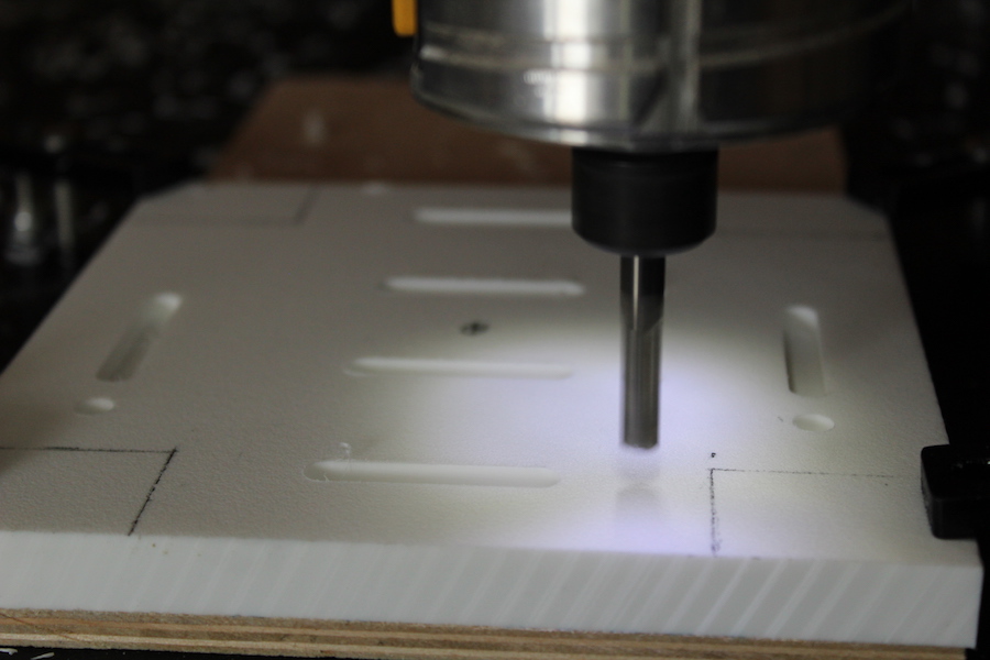
As the machine works through the operations, more and more material will be removed until the job is complete, this will be a messy operation.
Do not worry about cleaning up the debris while the job is running, it's safer and easier (and less likely to interfere with the job!) if you simply wait until the job completes to vacuum up the chips.
When the job completes, your machine will raise to the safe height (12mm above work surface) and then move to the back center position of the machine, moving the cutter away from the bed area for easy access to the workpiece.
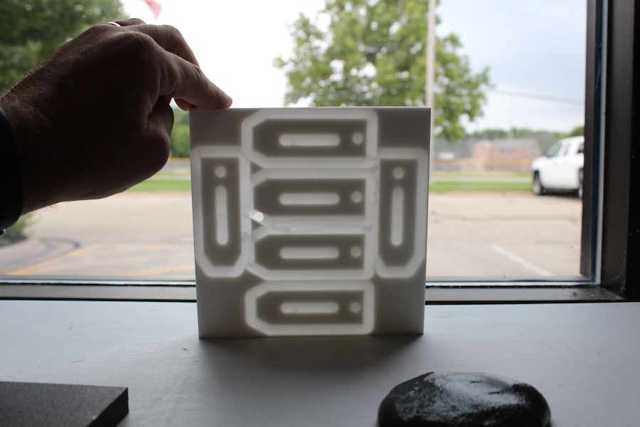
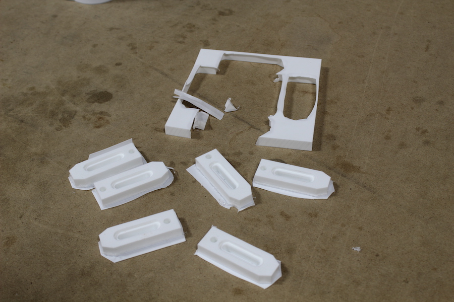
Shut the spindle down, and begin to remove your parts from the work area.
You should be left with something like this:
Finishing
We used a utility knife to cut the parts free from the material.
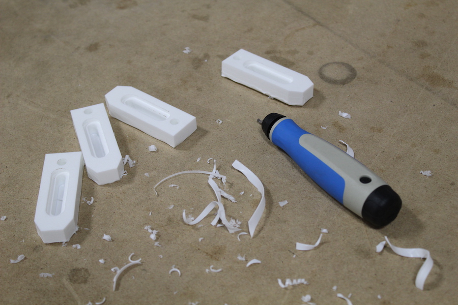
We used a regular deburring tool (like this one)) to do the final cleanup
The deburring tool makes it easy get nice straight clean edges. If you don't have one, they are highly recommended.
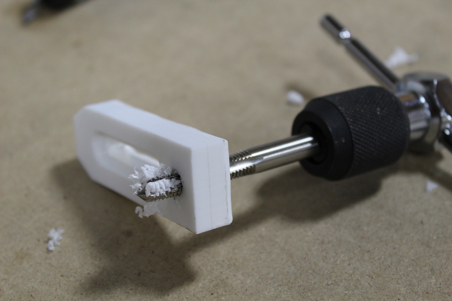
Although you could use threaded inserts for this part of the assembly, we opted to simply tap the hole for the jack screw with an M8 tap.
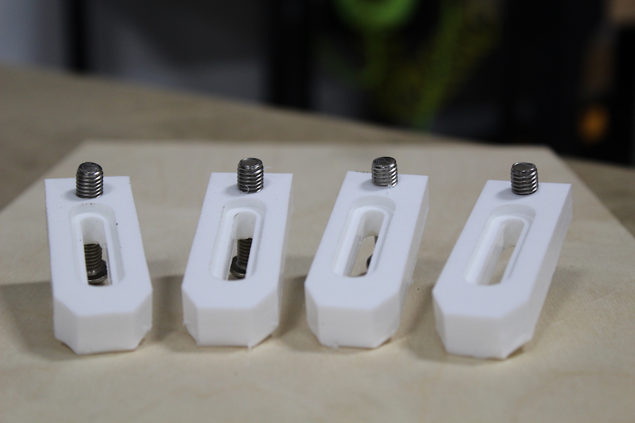
Complete
Here is the completed set of clamps! We opted to use M8 x 35mm button head cap screws for the ‘jack screw’, but a socket head would work just as well.
Pro-Tip: When you are clamping your parts down, the back end of the clamp (the end with the jack screw) needs to be higher than your material. If the back is not higher than your material, the downward pressure you create will be pushing more on the back of the clamp than on the material!
If you run into any problems or have questions, please email support@carbide3d.com for assistance.